After this I began to carry out the experiment. The output P.D with no weights added was first recorded; and then 50g at a time, the other weights were added, and the corresponding output P.D readings recorded. After numerous repetitions of this procedure (to minimize error), the process was repeated, but this time in reverse order. The output P.D was first recorded for the maximum weight used in the previous procedure, and then 50g at a time, weights were removed and the corresponding output P.D readings were recorded. This process was repeated a few times to minimize error.
Each time weights were applied to the sensor’s mechanical contact, I made sure not to force them down, but allowed them to rest freely on the contact, with the string drawn tight enough to hold the weights more or less straight upright, without restricting them in any way. This ensured that the conditions for the readings to be taken remained as close to constant as possible throughout the experiment, and so helping to improve accuracy.
Results
The final ‘raw’ results obtained from the experiment, are shown and compared in the following table, and presented visually in the graph which follows.
-Table Of Experiment Results
Analysis
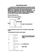
From the results you can clearly see that increasing the amount of mass applied to the mechanical contact, that is, the force applied to the mechanical contact, decreases the output P.D or voltage. As the mechanical contact experiences a force, it is pushed inwards, which consequently reduces the resistance of the sensor’s variable resistor. This therefore, in accordance with V= IR, produces a smaller output P.D or voltage. This type of circuit is known as a potential divider circuit, where the sensor’s resistance changes in response to the environment, (in this case an applied force) and so the proportion of the P.D across the sensor changes, which is used to give an output P.D or voltage. From the results we see that the maximum output P.D, is 4.95 V. This then means that at this point, the P.D across the fixed resistor (if first circuit) would be 0.05 V.
During the experiment, some anomalies were experienced. When carrying out the experiment by starting with a maximum weight and decreasing gradually, there was unusually low output P.D readings recorded, for the 950g- 850g masses. This however was identified to be because of the improper balance of the weights on the mechanical contact, which therefore gave inaccurate readings, as the conditions for the experiment changed. In light of this, we can make the assumption that the approximate operating force of the sensor is from 2.0 N to 7.8 N. This proves the relative accuracy of my experiment, as this assumption is very close to that of the manufacturers’, which was said to be 2.0 N to 7.5 N.
Also, after comparing the two sets of results and corresponding graphs, it was noticed that the output P.D readings of the sensor when gradually adding the weights, was higher for each amount of mass than those recorded when gradually decreasing the weights applied to the sensor’s mechanical contact. This could be because of random error; or possibly even systematic error, as an average difference of 0.05 V is seen throughout.
In the graph, we can see that there is a generally smooth curve throughout. It is hard to tell how accurate the results are. Firstly, much effort was put into making sure the weights were balanced on the mechanical contact in the same way throughout the experiment. However there is no guarantee, and is probably quite unlikely that each weight was balanced in the exact way as the one before. Also, due to the fact that the mechanical contact is not 100% efficient, that is, there would be some friction involved, this means that with lighter weights/force, detail or smaller changes are harder to detect, and therefore this explains the sudden jumps in output P.D readings for the lighter weights. An attempt was made to lesson the effect of the friction by the application of some WD 40, which helped to smoothen out the movements of the mechanical contact; however the problem of friction still was, and would be experienced. This then also relates to the sensitivity of the sensor, as gradual minor changes may not be detected as that itself, but rather as a big jump when it reaches a certain point.
Conclusion
From this experiment we can see that using a linear position sensor in a potential divider circuit gives an output P.D or voltage, relative to the changes in resistance, in response to the environment. An increase in the force applied to the sensor’s mechanical contact is associated with a decrease in the resistance of the sensor, and so the output P.D or voltage also decreases.
In light of this experiment, and other background research of this sensor, I believe that a contact linear position sensor would be ideal for automotive applications. This is because there needs to be a constant track of the positions of the engine compartments, especially the movement of the engine’s cylinders and pistons, and this sensor is protected against an engine compartment environment, (such as high temperatures), which can be harsh. It is also cost-effective, with a long endurance life, and can be ‘tailored’ and configured to fit the customer’s needs or specifications.
Here is a picture of the linear position sensor used in my experiment
By: Scott de Silvia