By powering all the segments, this will display the number 8. Powering a, b, c, d and g will display the number 3.
Numbers 0 to 9 can be displayed and the d.p represents a decimal point.
Resistors must be placed in series with each diode to limit the current through each diode to a safe value.
Early wristwatches used this type of display but they used so much current that the display was normally switched off, so to see the time you had to push a button.
Common anodes displays where all anodes are joined together and go to the positive supply are also available. Liquid crystal displays do a similar job and consume much less power.
Alphanumeric displays are available which can show letters as well as numbers.
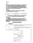
Figure 3A working common cathode 7-segment display http://coe.pitt.edu/courses/0501/web-docs/course-notes/fall2002/7Seg_Disp.jpg
System Specification
Upon completion, the system must be able to detect when a person comes into contact with the input sub-system. To be able to detect a person passing through a turnstile there would have to be a degree of sensitivity to pick up on light blockage from a distance.
The generated pulse from the input sub-system will then be counted in the process block device(s), the result count of ‘one’ is to be displayed on the output device, a seven-segment display. Lastly the system must be able to reset the counts at the end of use back to 00.
Relevant Parameters:
Possible Solution
Solution 1:
By creating a potential divider with the LDR and a variable resistor, an output/pulse is created which feeds into the BCD counter. The generated 4-bit code is then decoded by the decoder and displays a count on the seven-segment display.
Note the output would not be crisp and sometimes distorted and possibly not very sensitive.
Solution 2:
This is the same as the first solution but replacing the LDR with a phototransistor. This circuit could give a more sensitive and sharper pulse from its input circuit output.
Solution 3:
Again the same as the above two solutions but the input block again changed to a photo diode. The diode when in reverse bias has a fast response and will give a more accurate pulse.
Solution 4
To give a much clearer and definite pulse a switch could be used to provide an impulse to the BCD counter.
Solution 5
This type of switch is as explained earlier, designed to smooth out any bounce in the pulse, thus giving a clearer indication that a person has by-passed through the turnstiles.
Final Solution
I think the best solution to consider implementing would be solution number 1. It is simple and logical and within my skill level in terms of knowledge and experience in practical situations.
How this system will work is as follows:
- A person will pass the Light dependant resistor. Thus the resistance of the LDR is decreased and the output Voltage is high.
- This pulse is transmitted into a Divide-By-10 Binary Coded Decimal Counter where the pulse is made into a 4-bit code.
- This code is then transmitted into a 7-segment decoder drive where which the 4-bit code will be decoded.
- Finally to be displayed as a count of ‘1’ on a 7-Segment display.
Sub-System Development
LDR potential Divider Sub-system
This sub-system shall provide the pulse needed to be counted and will be simple to build. As the light on the LDR is blocked, the resistance of it will decrease and the resistance of the variable resistor increases so that most of the voltage is dropped across the LDR, thus giving a high output.
An output voltage of > 3.5V is required, as the CMOS chips require an input of 3.5V – 5V for it to switch to logic 1. When the LDR is in the light, the voltage would need to be at < 1.5V as the CMOS chips need to have input voltage levels at 1.5V or less in order to switch to logic 0.
Relevant Calculations
When LDR is in light:
In the shade, Vout will be:
These values suit the requirements of the CMOS chips as they require an input voltage of < 1.5V and the outcome form the above calculations provides that. Also for when the LDR is covered, the CMOS requirements is an input voltage of > 5V where the calculation above provides that.
Divide-by-10 BCD counter (CMOS 4510B)
This is the next sub-system of my device. This system will take the pulse from the input block. The pulse is counted and presented as a binary coded decimal (BCD) 4-bit code at the output.
BCD stands for Binary Coded Decimal. A BCD counter has four outputs usually labelled A, B, C, and D. By convention A is the least significant bit, or LSB. The easiest way to understand what a BCD counter does is to follow the counting sequence in truth table form:
When pulses are delivered to the CLOCK input (and all the other connections needed for basic operation are made), the outputs of the 4510 follow a sequence starting from 0 0 0 0 up to 1 0 0 1, the binary equivalent of the decimal number 9. The next pulse causes the 4510 to RESET and counting starts again from 0 0 0 0.
In other words, the counter outputs follow a binary sequence representing the decimal numbers 0-9.... this is why the 4510 is called a binary coded decimal counter.
To make the 4510 work, you need lots of connections. Every INPUT of a CMOS integrated circuit must be connected to something. The CLOCK input, for example, will be connected to the output of source of pulses such as a-stable. You will also need to connect all the load inputs, the carry in and the up/down input.
(pin out of CMOS 4510B)
BCD to 7-segment decoder
My next sub-system following the BCD counter is the 7-segment display decoder drive. Also form the CMOS logic family; the function of a BCD to 7-segment decoder is to convert the logic states at the outputs of a BCD counter such as the 4510B into a form that will drive a 7-segment display.
The display shows the decimal numbers 0-9 and is easily understood. The 4511’s are designed to drive a common cathode display and won't work with a common anode display.
7-Segment Display
My final sub-system is the 7-segment display. This is used to display the output from the converted logic states from the decoder drive. There are two important types of 7-segment LED display:
-
In a common cathode display, the cathodes of all the LEDs are joined together and HIGH voltages illuminate the individual segments.
-
In a common anode display, the anodes of all the LEDs are joined together and connecting to a LOW voltage illuminates the individual segments.
As mentioned above, the CMOS 4511 chip will only work with a common cathode 7-segment display.
When the 4511 chip is set up correctly, the outputs follow this truth table:
The 4511 produce a display without tails. If other binary values, greater than 1 0 0 1 are connected to the inputs of the 4511, the outputs are all 0's and the display is blank.
(pin out CMOS 4511 decoder drive)
The structure of the CMOS series chips is based on MOSFETS. CMOS stands for complementary metal-oxide semiconductor and has a supply voltage range of 3 – 18V. As mentioned in the previous page about the switching levels, for Logic 1, the input voltage needs to be above 70% of supply voltage. For logic 0 the input logic level needs to be below 30% of supply voltage.
Power consumption is < 1 μW and its switching speed is approximately 125nS with a high input impedance. They are static sensitive so must be handled with care and the unused inputs must be connected to + supply or ground. If unused ports left to float erratic behaviour will occur. The general noise immunity of the chips is good.
System Details
The following points analyse how the system will work:
-
As a person passes the LDR, light is blocked on the it decreasing its resistance resulting in a high output voltage > 3.5V from the potential divider circuit. This output is fed into pin15 of the 2nd CMOS BCD divide-by-10 counter.
- The pulse form the input circuit is received at the clock pin of the counter and where on every rising edge (LDR light blocked) a count of one is made and a 4-bit code is produced.
- The 4-bit code is sent to the 7-segment decoder drive where the code is decoded into a form, which will drive a 7-segment display.
- The decoded pulse is now to be displayed on a 7-segment display which is to display a count of ‘1’ in the units column and a ‘0’ to be displayed in the tens column until the units reaches ‘0’ again then a ‘1’ is displayed in the tens column (i.e. count of 10)
Power consumption of the circuit
Assessment of the complete system
Post testing of the system the outcome wasn’t good. Although all sub-system were constructed correctly and were working correctly the problem laid in the input sub-system. The LDR wasn’t sensitive enough as much as would have been ample and there was a switch bounce in the signal when the LDR was blocked. This caused the 7-segment displays to display counts in multiples instead of one by one as each time light was blocked. The other flaw in the system was the failure of the reset switch operation. Yet due to my lack of depth in knowledge I was unable to identify the reason behind the failure of it.
Yet as mentioned all sub-systems were working to their full effect. The process devices BCD counter and the decoder driver where working as the counts were being displayed on the 7-segent displays. To display the initial intent of the working circuit, I replaced the LDR potential divider circuit with a normal switch so to avoid the switch bounce. This produced a much clearer signal to the BCD counter and there were no multiple counts displayed. After doing so another flaw appeared, the tens and units columns seemed to have been constructed the wrong way round and the counts still were not registering correctly.
Limitations and modifications
I think the main limitation in the performance of the completed circuit is the input block for the LDR potential divider circuit. The LDR wasn’t sensitive enough to even detect a person walking past 1 cm away from the sensor. The sensor had to be covered totally to produce an impulse but still a switch bounce occurred as mentioned before. Another limitation is that I made a mistake in not testing each subsystem as I built it and carried out the necessary checks where they were applicable, had I done that a solution could have been identified to the problems that arose when testing the whole system.
An obvious modification to the circuit would be to the input block of the LDR potential divider circuit. If a Schmitt trigger was used in the potential divider circuit on the output, a finer signal would have been produced eliminating any switch bounce but not necessarily a more sensitive LDR. Another modification to be considered was using a pressure sensor i.e. a foot switch to produce a more sensitive pulse into the counter instead of an un-reliable LDR. A final modification is a result of a human error; each sub-system should be tested after construction to avoid problems.