When light strikes an electron, enough energy can be transferred so that it has enough energy to move to a free outer shell i.e. one that is not full. The electron below moves to an empty outer shell after the photon strikes it.
Note that this movement is continuous. The electron cannot occupy as shell that is already full. To this end, it does not stop as it passes through any of the other shells and if, as in this case the first shells are full, it will fall into a new electron level that was previously empty.
A voltage increase is seen across the LDR when bulbs of increasing Wattage are placed next to it.
Plan
The qualities which I have decided to investigate are Resolution, Response Time, Sensitivity and I have also looked at Random Variation because of the equipment I have used (Digital Multimeter)
The type of sensor which I have decided to use is a light dependant resistor which is a passive sensor and I will place this in a potential divider circuit.
The main aim is to investigate the characteristics of the LDR though. I will also be looking at the affect of light intensity on the resistance through an LDR.
Apparatus:
-
Digital MultiMeter (Ohmmeter) – more accurate than using a voltmeter or an analogue measurement instrument at times
-
Wires/leads – to connect the experiment
-
Voltmeter – to measure voltage
-
Wooden Metre Rule with mm Scale – easy to measure a large range of distances and does not expand like metal or plastic rulers when exposed to heat
-
Scissors - to cut open the top and sides of the box so that it is easier to manoeuvre around the experiment
-
Cellotape – to tape down the LDR to the box and mark out distances
-
Light Dependant Resistor and Resistor - I have used the LDR to detect the levels of illumination in the experiment. I decided on this resistance of LDR and Resistor as they are of very close values and produce a potential divider circuit of appropriately high sensitivity
-
2 Power Packs - In this experiment I used a separate power supply for the potential divider circuit and the light source. My reason for implementing this is that the resistance of the potential divider circuit could affect the intensity of light emitted by the bulb, thus producing unreliable results.
-
Light Bulb – to apply light to the LDR
-
100 k Ohm Resistor – to serve as a resistor in the potential divider circuit
-
Large Box – reason listed above under ‘Use of Physics’
-
Black Non Shiny Paper - reason listed above under ‘Use of Physics’
Safety
- Main safety point is that the Power pack plugs into the mains and therefore care should be observed while using
- Power pack must be fitted with a fuse and/or safety cut-out button
- Correctly connect all the components and check the wires before hand for any cuts or naked wires.
- Place all equipment so that it is not cramped or near the edge as this can lead to falling or causing accidents
Circuit Diagram:
The LDR:
'Success in Electronics' (Tom Duncan 1983) provides this symbol as the representation of an LDR and tells us that this component, sometimes called a Photo resistor, varies its resistance according to light levels. The resistance of an LDR depends upon the amount of Charge Carriers inside the component. Charge carriers are particles which are capable of carrying charge and are free to move across electron levels.
According to Ohm's law, the resistance falls in the LDR as the current throughout the circuit increases. The reason for this increase in current is due to the greater number of charge carriers in the semi-conductor inside the resistor. In this case, the charge carriers are electrons.
This increased number of electrons when light intensity increases, raises the semi-conductor's Conductivity and therefore lowers its Resistivity as the two values are inversely proportional.
It is only reasonable to say that as the current through the circuit increases, therefore so too will the voltage across the LDR.
My calculations and my research tell me that as the energy from light (photons) falling on the surface of an LDR is used by the semiconductor material to make more charge carriers available, so its resistivity falls as the level of light rises.
I would expect a graph of resistance against light intensity to look something like the below:-
Finding the Sensitivity of the LDR
Method
- Set up apparatus as shown below:
- The apparatus must be placed where no other light sources can interfere with the experiment such as in a dark-room.
- Switch on the bulb. Allow 5 seconds before taking a reading. This gives the filament time to fully heat up, so the bulb is at maximum intensity.
- Record the current reading on the Multimeter from distances starting from 20 cm and going up to 60 cm in 5cm intervals.
- The entire experiment should be repeated twice more in order to ensure consistency in the results by changing the power pack voltage supplied from 3 Volts to 4 Volts and then to 5 Volts.
- Plot graphs of the results.
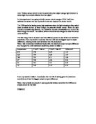
Results
Analysis
The graph starts off high and swoops down low this means if the distance is short then there is a larger amount of light goes on to the LDR, so there are lots of electrons that are being released, so there is a high current. Then if the distance is further away from the light then there is a small amount of light goes on to the LDR, so there is fewer electrons that are being released, so there is a low current.
The graph also satisfies my hypothesis that as the light intensity rises, the resistance falls. This is shown by the levelling off of the curve.
Calculating Voltage Output from 20cm Away and 60cm Away for 3 Volts Supplied
Therefore, this circuit gives a LOW voltage when the LDR is in the light and a HIGH voltage when the LDR is in the shade. The voltage divider circuit gives an output voltage which changes with illumination.
A sensor subsystem which functions like this could be thought of as a 'dark sensor' and could be used to control lighting circuits which are switched on automatically in the evening.
Finding the Response Time of an LDRMethod
- Set up apparatus as shown below:
- Place the cardboard box on top of the lamp and the LDR
- Place the Lamp 10cm away from the LDR
- Cover the LDR with a paper stuck to a pencil for example as a swivel device that can be removed almost instantaneously
- Record the time taken for the current to change and stabilise (the value of the current is not necessary in this circumstance)
- Repeat steps 3, 4 and 5, but from 20cm away and 30away
- Plot a graph of the results
Analysis
‘Response time has to do with how fast a system changes from one state to a different state. Response time is the time taken by a system to change after a signal initiates the change ‘.
The response time for my sensor was very quick for each distance respectively. It can easily be recognised from my results table and the above graph that the relationship between response time and distance away from LDR is that the response time to detect the change increases as the distance from the LDR increases.
I was expecting this result before I tested because current has to travel across the whole circuit and if the distance increases, the current has to travel a greater distance therefore the response time increases slightly.
Finding the Resolution of an LDRMethod
- Set up the equipment as shown below:
- After making the distance from the light bulb to the LDR 50mm and ensuring that the Voltage stays constant on 4.00 Volts, slowly move the LDR away millimetre by millimetre until the voltage changes to 4.01 Volts
- Record the distance in millimetres that the LDR was moved to attain the change of 0.01 Volts.
- Repeat this 2 more times
- Then make sure the voltage is 4.01 Volts, increase the distance the LDR is away from the light bulb by 50mm and repeat steps 2, 3 and 4 for the 0.01 volt change
- Do the same for 4.02 to 4.03 volts and 4.03 to 4.04 volts, repeating steps 2, 3 and 4 for both, making sure to move 50mm away the LDR from the light bulb each time
- Take averages of the 3 distances the LDR moved for each distance away and plot a table of results and a graph of the distance moved away against the average resolution
Analysis
Due to the nature of the equipment that I have used in this investigation, the resolution of my sensor is 0.01 Volts. This is the smallest measurement that the voltmeter used would facilitate. The digital multimeter could take the voltage to 3 decimal places but the random variation and fluctuation of the sensor made it impossible to take accurate measurements to 0.001 Volts, therefore the resolution is in fact 0.01 Volts, as this can be detected with the fluctuation.
EvaluationI found that a 100k Ohm resistor did not suit my purposes best. I should have used a 1k Ohm resistor ideally. If I used a resistor lower than 1k Ohm the resistor would tend to burn out or give wide-ranging results making the difficult to graph, and the voltage changes in larger resistor are to small to measure given that the digital voltmeter is only precise to 3 significant figures. The 100k Ohm resistor was too large and this is why my results are large and relatively inaccurate to see a specific pattern in the results.
Also when trying to record the results for resolution, I noticed that there was random error and the voltage recording had small unpredictable variations in quantities. ‘In measurement, when accidental variations with known or suspected causes have been eliminated, systematic error has been allowed for, and no trends in the variations appear, variations of measurements around a central value are often treated as random errors.’
Systematic drift is also evident in the resolution experiment as nearly all results for each distance are different apart from one result. This can be countered by taking 3 or more results for each distance and taking an average, this way the amount drift affects the results and trend in a graph is very slight.
Conclusion
Had I more time I would like to examine the voltage across the LDR when exposed to lights of different frequencies i.e. all the colours in the spectrum. Since we know the frequencies of all the colours of light, it would be possible to prove a definitive link between light frequency and the amount of energy transferred. If we wish to talk about the Quantum aspects of this experiment, this experiment goes a long way to prove that light has particle-like properties as the amount of energy needed to make an electron move from one level to another is fixed and yet the light seems to provide this exact amount every time it falls on the atom. Essentially, the electrons are receiving a certain amount of energy each time. It could be that every single light 'wave' contains an identical amount of energy or it could be true that single photons are delivering an exact 'packet' of energy to allow the electrons to become Charge carriers.
Use in Industry
In order to convert the sensor I have designed, into a device fit to operate as a switch for apparatus such as a street-light, many modifications would be required. The sensor operates only when needed, so it must be calibrated to engage at the correct resistance (potential difference reading). In order to determine the correct levels for this function, preliminary experiments will need to be carried out. For example, taking voltage readings at the intensity level of light for which the device will be required to illuminate at. The sensor would require a computer that uses a look-up table in order to use this data. I would suggest that the device is situated in a place that will not be influenced by the street lamp itself. The ideal place for this would be on the top; however other precautions will need to be taken to ensure its success. These would include carefully situating the lamp, to prevent the light being obstructed from the sensor by trees etc.
Bibliography
‘Success in Electronics’ book by Tom Duncan for a detailed account into the physics of a Light Dependant Resistor
‘Advanced Physics’ book by Steve Adams and Jonathan Allday for background research into an LDR and the patterns in graphs
Advancing Physics AS version (CD ROM) for help on defining certain terms, searching patterns in graphs and project ideas
Physics tutor for advice on what experiment I should choose
for research on the characteristics of an LDR and equations to calculate voltage