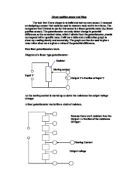
Circuit
Equipment Needed
A beaker (1000ml), Power supply (6v), Plastic float, Voltmeter, Wires, Automatic rain ganger (different resistor), Measure cylinder, Fixed resistor.
Theory
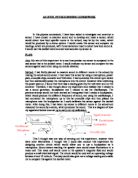
I am going to choose a fixed resistor for the circuit. It has to be the middle value of the resistor for my water lever sensor. So is work for my potential divider (voltage share = resistance share) because I’m using 1000ml beaker, put the water up to 1000ml and 0ml. get the resistance through an ohmmeter. So I have a max and min value of the resistance. This is max (1.58Ω) and min (0.31Ω). Then I work out the middle value of it (max+min)/2= (1.58+0.31)/2=945Ω. I find the closest fixed resistor which is 948Ω. To validate I used voltmeter find the voltage cross fixed resistor and the sensor when the water at max level. 2.25v and 4.27v which is close to the value it should be. at max level the sensor should get two times the voltage than the fixed resistor. Because this is a potential divider (voltage share = resistance share) there is more resistance on the sensor so more energy is needed to pass the resistor therefore more voltage they get.
For reading, I need to remember when I read the level of water or any liquids, I need to read the dip of water level and my eyes should at the same level as the dip of water.
I won’t use any data which are not very accurate. All my results and calculations will be in 2 significant figures.
Safety
My circuit is perfectly safe because before doing the research I checked every wire and found there was no problem. The power supply was the batteries which were 1.5V for each and I got 4. So the total voltage was (1.5*4)V which was less than 38V, so it was safe for humans. The water was clean and it was not harmful to people. The beaker was 1500ml big, but I only used 1000ml, because if I used 1500ml the water would easily overflow.
Experiment
I connected the equipments and checked does each one work well and turned the voltmeter to 20. Then I started my experiment. I put 100ml water into measuring cylinder and looked the dip of the water to make sure it is accurate. Then I poured them into the beaker. I took down each voltage for corresponding water level. I took 3 set of reading so I could have an over all average latter on.
Then I got two rulers to measure how high each ml was and tried to make it more accurate, I put one of them in the beaker and another one at outside which was used for measure. Because the base of the beaker was not horizontal so the first one was used to make sure the second ruler got the right position and could make the inaccuracy smaller.
There was about 0.8cm per 100ml. So I can calculate the height of any levels and reduce the inaccuracy.
Problem & Improvement
Firstly, there was a big problem I find. As soon as I pour the water in, the handle went opposite direction. So my reading of the voltmeter decreases. So I pour the water up to 1000ml first then taking water out from it each time. This dose take me a bit time but I managed in the end.
Secondly, the voltages would change by the position of the beaker and if it was closer to the stand, the voltage would be smaller because when the position changed, the position of the float changed as well. During the experiment, somebody including myself touched the beaker a little bit, and then I just got an inaccuracy.
Thirdly, in the experiment I found sometimes when the water level went up, the voltage went down. Normally it should go up because when the resistance was bigger, the voltage was increase. Then I found the reason. Sometimes when the level went up, the float moved to forward. Then it pulled the joint so the resistance was smaller.
Lastly the float always collides the wall of the beaker, so when the water level went up, the float didn’t work regularly and it affected my result of the voltage.
I support to solve the third problem in this way: I changed the float to a small ball, because the mass of the ball distribute symmetrical, the problem can be solved. Then I did the experiment in this way and the same problem did not happen. So the results were more accurate.
And if the beaker position changed, whatever the position of the float of the ball would be changed dramatically. So the results would be error and I need to do the experiment again. So I just put the beaker close the wall and if the position changed, I did not use the data for my investigation.
For the last problem, I just used my hands to move the float to the middle of the beaker. So far, the new problem would occur, because of moving the float, the position of the float would change all the time, so I should collect the data after a bit while waiting until the float stop moving any more.
Tables & Graphs
1st try
2nd try
3rd try
The total voltage should be 6, because my circuit is a series circuit. The reason I don’t get the total value to be 6 is that there is some resistance in the wire and there is an internal resistance between the batteries. Therefore using I know the point which they have same resistance between sensor and the fixed resistor which is about at 400ml. the voltage is close at this position. Also to workout the average value I add the value in my first three table divide by 3. This will give me more accurate answer.
Average
Evaluation
Alternative method:
I can hardly find any alternative method for the water level sensor. that makes it more important to us. Is the best way to get accurate result in detecting water level changes inside the oil tank.
Anomalies:
The best line fit is not very accurate is because I’m using a very small Measure cylinder some time the Plastic float hit the side of the cylinder. Make my reading less accurate than it should be. I would have achieved better information using a big cylinder.
Sensitivity:
Sensitivity is known as the gradient of the graph:
Change in voltage / Change in the depth of the water
(3.49-2.34)/(800-200)=1.92×10-3v/ml
Response time:
My sensor was different to other sensors; the response time was real quick in the sensor. When the level of water changed the water pushed the float up and the resistance of the Automatic Rain Gauge changed, then I knew how many the voltage changed form the voltmeter. I didn’t take the time of response because when the water level went up, the voltage changed very quickly and I was not able to take the data.
Resolution:
Resolution is the smallest change that is measurable by the sensor. And the smallest reading voltmeter could get is 0.01v when the voltmeter set at 20v.
Resolution when voltmeter set at 20:
0.01/1.92×10-3=5.23
Conclusion
Water level sensors are one of the sensors which are not different to control but quite useful for our life. Because water is one kind of liquids, we can change water to other liquids, which is the liquid we want to investigate.
My experiment investigated how it worked and proved the potential divider circuit. I sum up the data and did some graphs to show the relationship between the level of water, resistance and the voltage. However there are some inaccuracies because we cannot find the exactly data for the levels when the water was in the measuring cylinder. The only thing we can do just try our best to reduce the inaccuracy. Anyway, I reduced the inaccuracy to the smallest, so my experiment was successful. Also my sensor has a very quick Response time, high sensitivity and good Resolution, which is just good for the oil tank.