Furthermore, increasing the cross-sectional area of the wire will result in a decrease in the resistance. As the width doubles, the chance of possible collisions is halved, as there will be two times the amount of space for the particles to travel in. For example, take a road with a certain number of cars on it. If the road has only one lane, it will easily become congested, and so the cars will move slowly. Add an extra lane, and the cars will be able to spread out between the two lanes, therefore the cars can travel quicker. The same happens with metal conductors. The more electrons in the wire, the more crowded it becomes. This indicates that there will be more collisions so the resistance will increase. If the same number of electrons is given more space (doubling the cross-sectional area) they are able to move without too many collisions, so the resistance goes down. Say, for instance, that there are ten cars in one lane. Add another lane and the number of cars in each goes down to five, so the cars will be able to move twice as quickly due to half the amount of congestion. When the cross-sectional area of a wire is doubled, the electrons have twice the amount of space to travel in, and so the resistance is halved. This implies that resistance is inversely proportional to the cross-sectional area.
Experiment One: Investigation into how varying the length of a wire will affect its resistance
Fair Test:
In order to ensure that the experiment is as fair as possible, only one factor will be varied: the length of the wire. The other factors will be kept constant as shown below:
The cross-sectional area will be kept constant (at 38 SWG (standard wire gauge) or 0.0181mm²), as this factor will be explored in Experiment Two.
The material of the wire will also need to be kept constant throughout, and I have chosen to use Constantan wire, as this was the material that provided me with a larger quantity of widths to test in the experiment investigating the cross-sectional area due to lack of resources.
The temperature of the wire at the start must be the same to make it a fair test, and so each test should be done in the same environment at room temperature, as if there was a fluctuation in the starting temperature the electrons would have more energy and so this would have an effect on the resistance.
The current passing through the circuit must also be kept the same, as a change in the current may cause a sudden rise or drop in temperature that would end in a confusing set of results.
Method:
Safety:
Precautions must be taken so that no water gets near any of the electrical appliances.
It is imperative that you do not touch or place loose wires onto the wire that is being tested as it becomes hot during the experiment.
Leave the wire after the experiment for a brief period in order to let the wire cool.
Apparatus:
- Varying lengths of Constantan wire (as designated in plan) to be tested
- Rheostat
- Power supply
- Voltmeter
- Ammeter
- 2 connecting wires with crocodile clips
- 4 connecting wires
- A 1 metre ruler
- Scissors
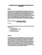
The following circuit was used in the experiment investigating length:
Plan:
- Connect circuit as shown in diagram above.
- Insert first length of wire, 10cm, into the circuit.
- Turn on power supply and take readings from both the ammeter and the voltmeter.
- Repeat until all following lengths have had readings taken:
- 20cm
- 30cm
- 40cm
- 50cm
- 60cm
- 70cm
- 80cm
- 90cm
- 100cm
The power supply was built so that 6 amps was the maximum current to pass through the circuit. I chose to set the potential difference at 4 volts as a compromise between 2 volts and 6 volts, as I felt that the former would not give a clear graph and I consider the latter to be too much as the wire may become too hot.
Then the whole experiment must be repeated 3 times for accuracy.
To ensure that the experiment is as accurate as possible, the lengths of wire must be measured from the inside of the crocodile clips, and the wire must be held straight when conducting the experiment. Any bends or twists in the wire may result in a short circuit or affect the resistance so that the readings would not be accurate.
Upon completing the circuit, the readings for potential difference (voltmeter) must be taken quickly because when current is passed through the conductor, the wire will begin to increase in temperature. The measurements must be taken promptly so that they reflect the resistance when the heat is affecting the wire the least (at the beginning).
Upon testing the experiment I have come to the conclusion that the plan will produce accurate readings and very few errors. With it, I was able to obtain these results:
Results:
Observations:
I observed that both the readings on the voltmeter or ammeter were not precise measurements, and kept flicking from one number to another, so I used the first reading, as I thought that this would be when the wire would be least affected by temperature, and then worked out the average (as shown above) from the three tests.
I was not able to obtain accurate results from the 10cm length of wire as the wire became very hot very quickly, so, as this would invalidate the results, I decided not to include it in my findings.
Anomalies:
There were no obvious errors in my experiment.
Conclusions:
In view of my results and the graph I was able to construct from them, I have made the following conclusions:
- As predicted, when the length of the wire increased, the resistance also increased.
- The graph shows a strong trend forming a straight line, showing that the length is directly proportional to the resistance; as the length doubles the resistance doubles as well.
From my analysis, I can confidently say that my prediction was correct. From studying the manner in which electricity is conducted, one can explain why the length of a wire is directly proportional to the resistance.
The number of freely mobile electrons in a given length of wire will produce a specific amount of resistance. This is because as a current is passed through the conductor the electrons in the outer shells of the particles are given energy so that they can move. As they travel through the wire, they come into contact with impurities in the conductor, other particles and any immobile material with which they ‘bump’ into. This collision releases some of the electrical energy as heat energy, which is then lost to the surroundings. When the given length is doubled, this means that there is double the amount of mobile electrons, and so double the chance of a collision. As an electrical current is passed through the conductor, an electron has to travel double the distance, and will therefore have two times the amount of objects in its path. Because there is twice the amount of collisions, there will also be twice the amount of electrical energy being converted into heat, and so the resistance doubles.
From these results we can work out the resistivity of Constantan wire:
R = ρl /A
This can be rearranged to make the resistivity (ρ) the subject:
ρ = RA/l
ρ = (6.93Ω x 0.0181mm²) /200mm
ρ = 0.125433Ωmm²/200mm
ρ= 0.000627165/1000 (to obtain ohm-metres)
ρ= (6.27 x 10⁻⁸) Ωm
Evaluation:
There were very few mistakes in my experiment, as is shown by the straight line on the graph, but I have several things to consider while evaluating my experiment:
- Although my circuit included a rheostat to control the current, the current through the wire varied dramatically, and this will affect the temperature of the wire. If the readings for current and voltage were taken immediately after the circuit was connected, these fluctuating currents should not have interfered with the results. However, if the reading on the ammeter or voltmeter was not taken quickly, the temperature may have risen, and therefore the resistance of the wire would have increased too. This would mean that the results would not be totally accurate, as the experiments would not be fair.
- There may have been some problems with the equipment that would help explain possible anomalies other than human error. For example, the wire used may not be pure, and the equipment was not totally accurate, due to frequent use, and the fact that it was built and maintained to a poor standard.
- As different lengths of wire needed to be used, I cut separate lengths of Constantan wire, instead of using the same section of wire and varying the points at which the crocodile was connected. It is probable that each separate section of wire had different amounts of impurities in them, and therefore the readings will not be entirely accurate.
- Some of the anomalies will have been caused by human error in the measuring of the wire. This is because it is not very practical to hold a piece of wire straight and cut it perfectly at the designated length. The crocodile clips will also have not been placed exactly at the specific length, and so the actual length of the wire in the circuits will vary from the length recorded.
- The crocodile clips used were partially rusted in places, and that would have prevented them from forming a good connection with the wire. They were not connected securely as they were old and much used so that the clips could be easily moved to alter the length.
Although there were many chances for an error to occur, there are none that obviously stand out. I do not feel, however, that the use of a thin wire in this experiment was a suitable choice, as the wire was never truly straight. It would be better to use a less malleable metal material, such as a bar, or in fact just to use the rheostat, as it is a long piece of coiled wire that can be connected at different lengths to change the resistance of the circuit.
Experiment Two: Investigation into how varying the cross-sectional area of a wire will affect its resistance.
Fair Test:
In order to ensure that the experiment is as fair as possible, only one factor will be varied: the cross-sectional area of the wire. The other factors will be kept constant as shown below:
The length of the wire will be kept constant at 40cm, as this factor has been explored in the experiment investigating length.
I will be using Constantan wire throughout, as there were a larger variety of thicknesses available to me with this material.
The temperature of the wires at the start must be the same so as to guarantee that a fair test is carried out. The temperature must be kept at room temperature, so that the electrons in the wire are not given differing amount of energy.
Method:
Safety:
Precautions must be taken so that no water gets near any of the electrical appliances.
It is imperative that you do not touch or place loose wires onto the wire that is being tested as it becomes hot during the experiment.
Leave the wire after the experiment for a brief period in order to let the wire cool before touching.
Apparatus:
- Varying cross-sectional areas of Constantan wire (as designated in plan) to be tested, all 40cm in length
- Rheostat
- Power supply
- Voltmeter
- Ammeter
- 2 connecting wires with crocodile clips
- 4 connecting wires
- A 1 metre ruler
- Scissors
The following circuit was used in the experiment investigating the cross-sectional area:
Plan:
- Connect circuit as shown in diagram above
- Insert first cross-sectional area of wire to be tested into the circuit, in this case: 22 SWG.
- Turn on the power supply and quickly take readings from both the ammeter and the voltmeter.
- Repeat until all the following thickness’ have been tested and have had readings taken:
a. 22 SWG
b. 26 SWG
c. 28 SWG
d. 32 SWG
e. 34 SWG
As already mentioned in the experiment investigating length, the power supply used was built so that 6 amps was the maximum current allowed to pass through the circuit, and again I chose to set the power pack on 4 volts.
The whole experiment must be repeated 3 times for accuracy, and then an average of these will be taken and used in the results table and graph.
To make sure that the experiment is as accurate as possible, the wire being tested must be held straight, so that it does not come into contact with anything but the crocodile clips, and so that there are no bends in the wire. This is to ensure that it does not short circuit or affect the resistance, so as to make certain that the readings are not jeopardized.
The readings must also be taken quickly after completion of the circuit, so that the current passing through the wire does not affect the temperature, and possibly resulting in an increase in the resistance that will provide confusing results.
Upon testing the experiment I have come to the conclusion that the plan will produce accurate readings and very few errors. With it, I was able to obtain these results:
Results:
The standard wire gauge (SWG) can be used to find out the radius. From this we can use the formula below to work out the cross-sectional area in mm²:
πr²
Observations:
Again, as in the first experiment, I noticed that the readings on the voltmeter and ammeter flickered between numbers, and so I took the first number as the most accurate measurement due to the effects of temperature change.
At the beginning of the experiment I was also going to test a Constantan wire of 30 SWG, but when testing this wire it provided me with the same results as that of 32 SWG. This probably meant one of the wires was marked incorrectly, so I only used one of them and marked it as 32 SWG as this followed the curve of my graph.
Anomalies:
The graph implies that my reading for the resistance of the 28 SWG wire was incorrect, as it differs about 0.85 Ω from my line of best fit. This is probably because the wires were mixed up (as this had already occurred), as the result for this wire fits in with my line of best fit for a thickness of about 31 SWG.
Conclusions:
In view of my results and the graph I was able to construct from them, I have made the following conclusions:
- As predicted, when the cross-sectional area of the wire increased, the resistance also increased.
- The graph shows a strong trend forming a curved line, showing that the cross-sectional area of a conductor is inversely proportional to the resistance (as shown in the graph recording the reciprocal of the cross-sectional area): as the cross-sectional area doubles, the resistance will halve.
From my analysis, I can say that my prediction was correct. This can be proved by carefully studying both electricity and electrical conductors.
Electricity is the flow of energy from one place to another. Metal electrical conductors enable energy to be passed through them by containing a ‘sea’ of freely mobile electrons, which carry the energy. When the electrons in the conductor are given enough energy, they are able to move from one end of the conductor to another, and therefore create a current. There is only a certain amount of space for the electrons to move in the conductor, and so collisions may occur between the electrons and any other immobile particles contained in the conductor. If the width (cross-sectional area) of the conductor, in this case a wire, is doubled, the electrons have double the amount of space, and so the probability of a collision between the electrons and any immobile or impurities in the wire is halved. This means that half the amount of electrical energy is being converted into heat energy by collisions, and so the resistance is also halved.
Evaluation:
There were a few mistakes in my experiment, mainly caused by carelessness in the storage of the materials used:
- I included a rheostat in my circuit, but I did not adjust it for each reading (to control the current) as I believed that leaving the circuit connected for a long period of time would considerably alter the temperature of the wire, as collisions occurred and electrical energy was converted into heat, so the current readings vary slightly, which I believe will produce varying temperatures, but none so dramatically as to render my results totally inaccurate.
- However, I attempted to take the readings for the ammeter and voltmeter quickly so that any temperature change would be very slight and would not affect the results.
- There were some problems with the equipment I used throughout this experiment. The apparatus was not totally accurate as it was built and maintained to a poor standard due to lack of funds, for example the crocodile clips were coated in rust, and so the contact between it and the wire was not perfect. The wires were labelled incorrectly so the results were confusing.
- Some of the anomalies will have been caused by human error in the measuring of the wire. This is because it is not very practical to hold a piece of wire straight and cut it perfectly at the designated length. The crocodile clips will also have not been placed exactly at the specific length, and so the actual length of the wire in the circuits will vary from the length recorded.
Although there were a few mistakes in this experiment, on the whole I do believe that they provided me with a good basis for my conclusions.