This paper begins with a review of the relevant psychoacoustic principles. The ATRAC encoder is then described in terms of time-frequency splitting, quantization of spectral coefficients, and bit allocation. Finally, the ATRAC decoder is described.
2 Psychoacoustics
2.1 Equi-loudness Curves
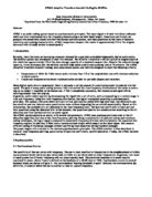
The sensitivity of the ear varies with frequency. The ear is most sensitive to frequencies in the neighbourhood of 4 kHz; sound pressure levels which are just detectable at 4 kHz are not detectable at other frequencies. In general, two tones of equal power but different frequency will not sound equally loud. The perceived loudness of a sound may be expressed in sones, where 1 sone is defined as the loudness of a 40 dB tone at 1 kHz. Equi-loudness curves at several loudness levels are shown in Figure 1. The curve labeled "hearing threshold in quiet" indicates the minimum level (by definition, 0 sone) at which the ear can detect a tone at a given frequency.
These curves indicate that the ear is more sensitive at some frequencies than it is at others. Distortion at insensitive frequencies will be less audible than at sensitive frequencies.
2.2 Masking
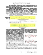
Masking [7] occurs when one sound is rendered inaudible by another. Simultaneous masking occurs when the two sounds occur at the same time, such as when a conversation (the masked signal) is rendered inaudible by a passing train (the masker). Backward masking occurs when the masked signal ends before the masker begins; forward masking occurs when the masked signal begins after the masker has ended.
Masking becomes stronger as the two sounds get closer together in both time and frequency. For example, simultaneous masking is stronger than either forward or backward masking because the sounds occur at the same time. Masking experiments are generally performed by using a narrow band of white noise as the masking signal, and measuring the just-audible level of a pure tone at various times and frequencies. Examples of simultaneous masking and temporal masking are shown in Figure 2 and Figure 3 respectively.
Important conclusions may be drawn from these graphs. First, simultaneous masking is more effective when the frequency of the masked signal is equal to or higher than that of the masker. Second, while forward masking is effective for a considerable time after the masker has stopped, backwards masking may only be effective for less than 2 or 3 ms before the onset of the masker.
2.3 Critical Bands
Critical bands [7] arose from the idea that the ear analyzes the audible frequency range using a set of subbands. The frequencies within a critical band are similar in terms of the ear's perception, and are processed separately from other critical bands. Critical bands arose naturally from experiments in human hearing and can also be derived from the distribution of sensory cells in the inner ear. Critical bands can be thought of as the frequency scale used by the ear [8].
The critical band scale is shown in Table 1. It is clear that the critical bands are much narrower at lower frequencies than at high frequencies; in fact, three quarters of the critical bands are located below 5 kHz. This indicates that the ear receives more information from the low frequencies and less from higher frequencies.
3 The ATRAC Encoder
A block diagram of the encoder structure is shown in Figure 4. The encoder has three components. The analysis block decomposes the signal into spectral coefficients grouped into Block Floating units (BFU's). The bit allocation block divides the available bits between the BFU's, allocating fewer bits to insensitive units. The quantization block quantizes each spectral coefficient to the specified wordlength.
3.1 Time-Frequency Analysis
This block (Figure 6) generates the BFU's in three steps, combining techniques from subband coding and transform coding. First, the signal is broken down into three subbands: 0-5.5 kHz, 5.5-11 kHz, and 11-22 kHz. Each of these subbands is then transformed into the frequency domain, producing a set of spectral coefficients. Finally, these spectral coefficients are grouped nonuniformly into BFU's.
The subband decomposition is performed using Quadrature Mirror Filters (QMF's) [0-10]. The input signal is divided into upper and lower frequency bands by the first QMF, and the lower frequency band is divided again by a second QMF. Use of QMF's ensures that time-domain aliasing caused by the subband decomposition will be cancelled during reconstruction.
Each of the three subbands is then transformed into the frequency domain using the Modified Discrete Cosine Transform (MDCT) [11-12]. The MDCT allows up to 50% overlap between time-domain windows, leading to improved frequency resolution while maintaining critical sampling. Instead of a fixed transform block length, however, ATRAC chooses the block length adaptively based on the signal characteristics in each band. There are two modes: long mode (11.6 ms) and short mode (1.45 ms in the high frequency band, 2.9 ms in the others). Normally long mode is used to provide good frequency resolution. However, problems may occur during attack portions of the signal. Specifically, the quantization noise is spread over the entire signal block, and the initial quantization noise is not masked (Figure 8a); this problem is called pre-echo. In order to prevent pre-echo, ATRAC switches to short mode (Figure 8b) when it detects an attack signal. In this case, because there is only a short segment of noise before the attack, the noise will be masked by backward masking (section 2.2). Backward masking is not effective for Long Mode because of its very short duration. Thus, ATRAC achieves efficient coding in stationary regions while responding quickly to transient passages.
Note that short mode is not necessary for signal decay, because the quantization noise will be masked by forward masking which lasts much longer than backward masking. For maximum flexibility, the block size mode can be selected independently for each band.
The MDCT spectral coefficients are then grouped into BFU's. Each unit contains a fixed number of coefficients. In the case of long mode, the units reflect 11.6 ms of a narrow frequency band; in the case of short mode, each block reflects a shorter time but a wider frequency band (Figure 9). Note that the concentration of BFU's is greater at low frequencies than at high frequencies; this reflects the psychoacoustic characteristics of the human ear.
3.2 Spectral Quantization
The spectral values are quantized using two parameters: wordlength and scale factor. The scale factor defines the full-scale range of the quantization, and the wordlength defines the precision within that scale. Each BFU has the same wordlength and scale factor, reflecting the psychoacoustic similarity of the grouped frequencies.
The scale factor is chosen from a fixed list of possibilities, and reflects the magnitude of the spectral coefficients in each BFU. The wordlength is determined by the bit allocation algorithm (section 3.3).
For each sound frame (corresponding to 512 input points), the following information is stored in disc:
- MDCT block size mode (long or short).
- Wordlength data for each Block Floating unit.
- Scale factor code for each Block Floating unit.
- Quantized spectral coefficients.
In order to guarantee accurate reconstruction of the input signal, critical data such as the block size mode, wordlength and scale factor data may be stored redundantly. Information about quantities of redundant data is also stored on the disc.
3.3 Bit Allocation
The bit allocation algorithm divides the available data bits between the various BFU's. Units with a large number of bits will have little quantization noise; units with few or no bits will have significant quantities of noise. For good sound quality, the bit allocation algorithm must ensure that critical units have sufficient bits, and that the noise in non-critical units is not perceptually significant.
ATRAC does not specify a bit allocation algorithm; any appropriate algorithm may be used. The wordlength of each BFU is stored on the MiniDisc along with the quantized spectra, so the decoder is completely independent of the allocation algorithm. This provides for the evolutionary improvement of the encoder without changing the MiniDisc format or the decoder.
There are many possible algorithms, ranging from very simple to extraordinarily complex. For portable MiniDisc recorders, however, the possibilities are limited somewhat by the fact that they must be implemented on low-cost low-power compact hardware. Nevertheless, ATRAC is capable of good sound quality using even a simple bit allocation algorithm, provided it is soundly based on psychoacoustic principles. ATRAC's nonuniform adaptive time-frequency structure is already based on psychoacoustics, relieving the pressure on the bit allocation algorithm.
One suggested algorithm uses a combination of fixed and variable bits. The fixed bits emphasize the important low-frequency regions, allocating fewer bits to the BFU's in higher frequencies. The variable bits are allocated according to the logarithm of the spectral coefficients within each BFU. The total bit allocation btot is the weighted sum of the fixed bits bfix(k) and the variable bits bvar(k). Thus, for each BFU k,
btot(k) = Tbvar + (1-T)bfix
The weight T is a measure of the tonality of the signal, taking a value close to 1 for pure tones, and close to 0 for white noise. This means that the proportion of fixed and variable bits is itself variable. Thus, for pure tones, the available bits will be concentrated in a small number of BFU's. For more noise-like signals, the algorithm will emphasize the fixed bits in order to reduce the number of bits allocated to the insensitive high frequencies.
The above equation is not concerned with overall bit rate, and will in general allocate more bits than are available. In order to ensure a fixed data rate, an offset boff (the same for all BFU's) is calculated. This value is subtracted from btot(k) for each unit, giving the final bit allocation b(k):
b(k) = integer{btot(k)-boff}
If the subtraction generates a negative wordlength, that BFU is allocated 0 bits. This algorithm is illustrated in Figure 10.
4 The ATRAC Decoder
A block diagram of the decoder structure is shown in Figure 5. The decoder first reconstructs the MDCT spectral coefficients from the quantized values, using the wordlength and scale factor parameters. These spectral coefficients are then used to reconstruct the original audio signal (Figure 7). The coefficients are first transformed back into the time domain by the inverse MDCT (IMDCT) using either long mode or short mode as specified in the parameters. Finally, the three time-domain signals are synthesized into the output signal by QMF synthesis filters.
5 Conclusions
Through a combination of various techniques including psychoacoustics, subband coding and transform coding, ATRAC succeeds in coding digital audio with virtually no perceptual degradation in sound quality. Listening tests indicate that the difference between ATRAC sound and the original source is not perceptually annoying nor does it reduce the sound quality. Furthermore, the system is sufficiently compact to be installed in portable consumer products. Using ATRAC, the MiniDisc provides a practical solution for portable digital audio.