The period of pendulum depends upon length (L) and the value of acceleration due to gravity (g), s described in the following equation
Rearranging this equation gives an expression that can determine g,
- Substitute your values for L and T into this equation to get g, which is the acceleration due to gravity.
-
The value of acceleration due to gravity at the surface of the Earth varies from the usually accepted value of 9.8 m s-2, due to a number of factors:
-
The Earth’s lithosphere varies in structure, thickness and density. Thickness variations are a product of the source and history of the material. Oceanic crust is thinner than continental crust. Continental crust is thickest under mountain ranges. Density variations occur due to the presence of concentrated and large mineral deposits or petroleum gas and related liquids trapped in sedimentary rocks and structures. All of these variations can influence local values of g.
-
The Earth’s globe is flattened at the poles. This means that the distance of the surface from the centre of the Earth is less at the poles, which increases the local value of g.
-
The spinning Earth also affects the value of g. At the equator, the spin effect is greatest resulting in a lowering of the value of g. As you travel from the equator to the poles, the spin effect on g shrinks to zero.
-
As a result of the above, the value of g at the surface of the Earth varies between 9.782 m s-2 at the equator and 9.832 m s-2 at the poles
-
The value of g reduces with altitude above the surface of a planet, becoming zero only at an infinite distance. At low Earth orbit altitude, the value of g is approximately 8.9 ms-2
PREDICTION
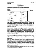
The diagram shows the arcs through which two pendulums swing. The red one is twice the length of the blue one. Notice that the short arc is always at a steeper angle than the longer arc, and always above it.
The shorter pendulum has the most gravitational potential energy at the top of the swing because it is higher. This means the kinetic energy and hence speed through the centre will also be greater than for the longer pendulum.
From previous trial experiments I know that for trolleys running freely down a ramp that the bigger the angle of the ramp the bigger the acceleration of the trolley. This same principle can be applied to the falling pendulums. The steeper the arc the bigger the acceleration of the pendulum will be. A bigger acceleration means a shorter time for each swing. Unlike a ramp the arc of swing is not a straight line. The arc has the steepest gradient at the top and is flat when it reaches the middle. The acceleration of the bob will thus decrease from a maximum at the top of the swing to zero at the centre.
For these reasons as the string gets longer the time per swing will get longer
RESULTS
GRAPH OF LENGTH AGAINTS T2
As can be seen the points plot into a straight line. A line of best fit was added to the chart as shown. The line can be sent to go through the origin as expected, it there is a tiny pendulum, it will have a tiny period and if there is an infinitely small pendulum, an infinitely small period. The gradient was calculated to be ¼ and this was inserted into the above equation to result in g=22π2¼. This equates to g=π2. As this is 9.8696 the experiment was remarkably accurate. The units of acceleration are ms-2 which agrees with the value above. It should be observed that the graph of length over time2 was plotted. The constants π and 2 have no units so have no effect
ESTIMATION OF UNCERTAINTIES.
Uncertainties while measuring the time period T, Systematic errors are introduced if my stopwatch is systematically off by a certain amount, and by delays due to my eye-hand reaction time. The stopwatch systematic uncertainty should be listed by the manufacturer of the instrument, whereas the eye-hand uncertainty has to be estimated by myself, e.g. by measurement against a known time interval. The statistical uncertainty on T comes from the fact that my eye-hand reaction time varies from one trial to the next; it fluctuates (around the systematic value). This statistical uncertainty can be reduced by making many individual (i.e. independent) measurements and averaging; the systematic uncertainty then decreases with the square root of the number of measurements: making 10 measurements will reduce the statistical uncertainty by a factor of about √(10) = 3.2
Errors
Actions taken to reduce the errors.
-Line eye up with fixed object for timing accuracy.
-Accurate stop clock (decimal seconds).
-Averaging two readings to remove human error
-Averaging twenty readings to improve accuracy b Y factor of 20
Over all the experiment was remarkably accurate as can be seen, with only 100(9.86-9.81)/9.81=0.61% error, 9.81 being the excepted figure.
0.61% Error
For extreme accuracy it would be needed to improve the method of timing the swings for example light gates and a computer (or other) timer/recorder. The length of the sting can also be found to a grater degree of accuracy with a micrometer or similar. Enclosing the apparatus in a vacuum box will negate all air turbulence effects. Releasing the pendulum is then a problem as the easiest and accurate method found so far is to displace the bob and tie it up with a thread. The system is then given time to settle and the thread is burnt, releasing the bob with minimum outside influence.
RELIABILITY
No significant problems or difficulties were encountered when carrying out this investigation. The accuracy and reliability of the results and conclusions are very good. Within the accuracy of the method used, and for the range of values investigated, it is clear that the time for a complete swing of the pendulum is proportional to the square root of the length.
IMPROVEMENTS.
The procedure used was simple and straightforward and no difficulties were encountered. A small improvement could be made to measuring the length of the pendulum. A longer rule, or piece of wood, could be placed level with the point of suspension, and a set square could be placed along the flat side and just touching the bottom of the pendulum. This distance could then be measured more accurately than trying to guess where the middle of the bob is. The diameter of the bob could be accurately measured with some vernier callipers so that the true length of the pendulum could then be calculated.
The thread used was quite stretchy. If the investigation were to be repeated I would replace it with something more rigid, such as extra strong button thread.
More repeats could be taken but I don't think this would add much to the accuracy of the conclusions.
Longer lengths could easily be tried, up to whatever maximum could be obtained. With a suitable location a length of several metres could be obtained. If the pendulum gets too long then stronger thread and a heavier bob might be needed. It would be interesting to try shorter and shorter lengths although a limit would be reached when the pendulum moves too quickly to be accurately counted. It may be possible to have some sort of electronic detection system that could automatically count and time the swings. Something like a light gate as part of a computer based logging system might work. An alternative might be a very high speed digital video camera that could accurately record the position of the bob and the elapsed time.
CONCLUSIONS
The time for one complete swing is proportional to the square root of the length. All the points for Graph lie on a straight line so the conclusion is very reliable over this range. It seems likely that the same trend would continue if the string were made longer. Shorter lengths look like they would also follow the same pattern although it gets more difficult to take the measurements as the time gets shorter. For very short lengths the trend may not continue and would be very difficult to measure. It is not possible to try lengths shorter than the diameter of the bob, for instance. A much smaller bob on a very fine and lightweight filament could be made and tested.
In terms of finding a value of g, the experiment can be deemed a success. The value found (9.8696 ms-2) was extremely close to the excepted 9.81 ms-2. If experiment were to be repeated, accurate timing gear would be a good investment, placing the apparatus inside a box to remove drafts would also be a good idea. For improvement of this experiment I could use different masses of the pendulum to get a slightly different value of the acceleration due gravity and averaging will give and accurate result.
I was able to predict that the time would increase but cannot prove that it is proportional to the square root of the length.
EVALUATION
Accuracy of Results
Measuring the length
One difficult part of measuring the length is deciding where the centre of the bob is. The uncertainty in determining this measurement is probably about 1 mm. Measuring the length beyond about 1 metre is more difficult than short lengths because the measurement has to be done in two parts using metre rulers. The total error in measuring the longest length (1 m) could be 2 or possibly 3 millimetres. For the shortest length the error is not likely to be more than a millimetre.
Adjusting the length of the pendulum to an 'exact' value such as 0.2m was not as difficult as I thought it would be. The cotton could quite easily be slowly pulled through the wooden blocks a little bit at a time until the measured length was correct. Had this not been possible, or to save a little bit of time, any value close to the required value would have been perfectly acceptable and would not have made any difference to the conclusions.
Measuring the time
The stopwatch measures to one hundredth of a second although the overall accuracy of the time measurements are not that good. The human reaction time to start and stop the watch roughly cancel each other out as the same event is being observed, and reacted to in the same way, each time. Errors are produced by any variability in the reaction time of the individual, which could be affected by many things. Taking more time measurements may give a slightly more accurate average for each length, but not by much. The smooth trend in the graph indicates that the results are accurate and reliable. There are no anomalous results or anomalies to be seen in the trend of the graph.
EXPERIMENT 2
FREE FALLING OBJECT
INTRODUCTION
The gravitational acceleration can be measured directly by dropping an object and measuring its time rate of change of speed () as it falls. By tradition, this is the method we have commonly ascribed to . In this experiment, Galileo is supposed to have dropped objects of varying mass from the leaning tower of Pisa and found that the gravitational acceleration an object undergoes is independent of its mass. He is also said to have estimated the value of the gravitational acceleration in this experiment. While it is true that Galileo did make these observations, he didn't use a falling body experiment to do them. Rather, he used measurements based on .
It is easy to show that the distance a body falls is proportional to the time it has fallen squared. The proportionality constant is the gravitational acceleration, g. therefore, by measuring distances and times as a body falls, it is possible to estimate the gravitational acceleration.
To measure changes in the gravitational acceleration down to 1 part in 40 million using an instrument of reasonable size (say one that allows the object to drop 1 meter), we need to be able to measure changes in distance down to 1 part in 10 million and changes in time down to 1 part in 100 million!! As you can imagine, it is difficult to make measurements with this level of accuracy.
It is, however, possible to design an instrument capable of measuring accurate distances and times and computing the absolute gravity down to 1 microgal (0.001 mgals; this is a measurement accuracy of almost 1 part in 1 billion!!). is one manufacturer of this type of instrument, known as an Absolute Gravimeter. Unlike the instruments described next, this class of instruments is the only field instrument designed to measure absolute gravity. That is, this instrument measures the size of the vertical component of gravitational acceleration at a given point. As described , the instruments more commonly used in exploration surveys are capable of measuring only the change in gravitational acceleration from point to point, not the absolute value of gravity at any one point.
Although absolute gravimeters are more expensive than the traditional, relative gravimeters and require a longer station occupation time (1/2 day to 1 day per station), the increased precision offered by them and the fact that the described later are not required to remove instrument drift or tidal variations may outweigh the extra expense in operating them. This is particularly true when survey designs require large station spacings or for experiments needing the continuous monitoring of the gravitational acceleration at a single location. As an example of this latter application, it is possible to observe as little as 3 mm of crustal uplift over time by monitoring the change in gravitational acceleration at a single location with one of these instruments.
SETUP
The second experiment is on a free falling object. The acceleration of gravity is measured by allowing a steel ball to fall, after starting at rest, and then applying the equation for accelerated motion. A free fall timer is used in this experiment. The figure below shows a brief mechanism of the experiment.
The figure above shows the experiment of the free falling body. It concerns with the length and time taken for a mass to travel the length. The experiment consists of a release mechanism, which release a mass (EG Metal ball), which then hits the pad of the base on the floor. The pad and the release mechanism are both connected to the timer, which calculated the time for the ball to travel the length. The timer should be connected to a power supply and should be brought back to zero for different lengths. When the ball is release the from the release mechanism it sets a signal to the timer which then starts counting in seconds until it receives another signal when the ball hits the pad on the floor the time stops which then give u the time for the distance traveled for a particular length chosen. While this may seem to be the most obvious method of measuring g, it was not practical until the advent of modern electronic timers. The acceleration of gravity is measured by allowing a steel ball to fall, after starting at rest, and then applying the equation for accelerated motion. A free fall timer is used in this experiment
PREDICTION
I predict that as the length, L increases the time taken would increase too because these variable are proportional to one another.
VARIABLE
The key variables of this experiment are:
- Length. The length between the release mechanism and the receiver pad of the dropping ball is a variable as it is crucial in determining the time taken for the ball to drop.
- Time taken, T is also a variable as it varies according to the length chosen by any person doing the experiment.
PROCEDURE
- Construct an experiment similar to the figure show above. And make sure the stand is clamped.
- Connect the release mechanism and the pad base on the floor with a timer.
- Place the both the releaser and the receiver of the ball at a desirable length and make sure the time on the stopwatch or a digital stopwatch (or any source of a timer) reads Zero.
- Test the experiment neglecting the time to check if the mechanism works
- Choose any length and record the time taken to travel the distance
- Repeat procedure 5 for different lengths and record a graph to give out averages of the time.
Use the data to find the acceleration due to gravity with the equation L=UT + 1/2G T²
Experiments show that, when air resistance can be ignored, all bodies fall with the same acceleration.
This acceleration is given the symbol g.
The acceleration due to gravity is not exactly the same at all points on the earth’s surface
Small variations in g are due to:
OBSERVATIONS
As u set up the apparatus as described above, you can see that the experiment is the simplest way to determine the acceleration due to gravity as we ignore the air resistance for this experiment. As the ball is release from the release mechanism this trigger digital timer. The time starts and stops back until the ball hits the pad which sends the message to the time to stop the time. The timer will give you the time taken, T for a particular length chosen.
THE THEORY BEHIND THE EXPERIMENT
Let
L= length (m); T= time taken; speed, V=L/T; G= acceleration due to gravity.
To calculate the acceleration due to gravity, take the time and length (distance) from the experiment and calculate the speed of the ball which is distance divided by time. Use the speed and time along with the distance to calculate G. by the following formula
L=UT+1/2G T²
Where U= initial velocity which is always zero in this case.
If U=0 then
L=1/2G T²
To find G
G=2L/ T²
TABLE OF RESULTS
From the results above, the acceleration due to gravity is fairly right as. It is almost close to 9.81, which is commonly used in calculation in physics. My results reflect to what I predicted before doing the experiment.
GRAPHS
The above graph shows that length is directly proportional to the time of the object fall. As the length increases the time taken also increases as predicted before.
The graph above proves that gravity is 9.81m/ s². You can calculate the acceleration due to gravity by calculating the gradient of the graph above. The graph shows an exponential curve because I have squared the time taken so as to get the acceleration due to gravity by the derived formula.
Even if we plot a graph of Velocity against Time the slope of the graph or the gradient would give us the acceleration due to gravity
SOURCES PF ERRORS
Sources of errors are always present for this experiment. We have neglected the air resistance, mass and many other variables which could help to find the accurate value of acceleration due to gravity. The sources of errors in my experiment were rounding off values which may vary the outcome of the results calculate with the formula. Some colleges do not have digital timers, which plays the major role as human reflex is not accurate as the digital timers. So human calculation may bring some error in your calculation
PROBLEMS
The problems that I faced while doing the experiment were as follows:
- Measuring the distance between the release mechanism and the receiver pad. I have planned to measure distance greater than 1m but measuring them was a problem as we only had access to meter ruler. To overcome this problem I had to take length less than 1m.
- The retort stand would not stay stiff which caused some time as I had find some heavy mass objects to support the retort stand.
- I also had some problems with the release mechanism, which would not hold the metal ball. So I had to tighten the plates in the release mechanism in order it to hold the metal ball firm and release it when the screw is turned to release the metal ball.
SAFETY
The safety for the ball drop method are common sense such as, providing yourself with a clear working area with no bags and no people playing around. Making sure that the electrical appliances are carefully operated and the wiring are perfect wired to protect oneself from being in contact with any of the wires which may cause a harm or irritation to the skin. Also making sure that you put your receiver pad in a box so that the metal ball does not get lost or cause accidents to other people in the laboratory. Handling the apparatus carefully because they are very delicate instruments to avoid damage and cots of the apparatus. Also make sure u turn out the digital timer while not doing your experiment to avoid overflow of current.
CONCLUSION
Overall the free falling object method was a fair and simple experiment to determine the acceleration due to gravity. From the results my acceleration due to gravity is about 9.8054 ms-2. According to the books the value of g is 9.81ms-2 that gives a difference of about 0.0046, to calculate the percentage error it comes to about 0.046%, which states clearly my experiment, is almost as accurate it can be. Therefore I conclude that my experiment to determine the acceleration due to gravity was successful and I have achieved my aim for this experiment.
EVALUATION
My experiment of the free falling object method to determine the acceleration due to gravity was very simple and straightforward. To improve my experiment I could have repeated this experiment several times then I could get more accurate results, which could have taken more time out of my schedules. So time was one of the limiting factors. To improve my experiment even further I could have used modern instruments to improve and get more accurate results and also I could have used other falling object with different masses to see how the value of g varies according to their masses. I could have also used different lengths between the release mechanism and the receiver pad but measuring the distance greater than 1m was a problem because I used meter rulers to measure my lengths of the experiment this was another limiting factor that I had to overcome by taking lengths less and equal to 1m.