The preliminary test showed a clear pattern that the resistance increases as the length of the wire increases.
Method
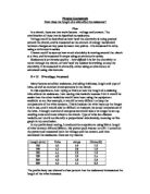
- Set up the equipment as follows:
- Clip the first 100mm length of 32 SWG nichrome wire between the crocodile clips, on top of the heatproof mat.
- Set the power pack to 4.5 volts. I chose this voltage because it gave a good range of results in my preliminary test and there was no reason to change it.
- Turn on the power pack and wait for the ammeter and voltmeter to settle.
-
Take voltage and current reading, then calculate the resistance using R=v/I.
- Swap the wire for 200mm, then repeat, and then again with 300mm, 400mm and 500mm. Then change the wire and do all the repeats twice more, to finish with 3 results for each of the 5 lengths.
I will keep my experiment a fair test in the following ways:
- Do not change nay parts of the circuit (wires, ammeter, voltmeter or battery pack) in between the measurements – this will prevent small discrepancies between circuit components from affecting the results.
- When taking the measurements from the voltmeter and ammeter, wait for the reading to settle completely. If it doesn’t settle, make an estimate of the middle value being shown. Waiting for the reading to settle will prevent accidentally taking a reading while the value is fluctuating randomly when the power is first turned on. Unfortunately, the equipment available to me is not the most accurate, so in some cases I had to make an estimate of the average.
- Use the same type and thickness of wire – 32 SWG nichrome – from the same reel for all the lengths and repeats, to ensure there are no slight variations between reels of wire.
- Use 3 different samples of wire for the repeats of each length, instead of the same sample 3 times. This will avoid the wires increasing in temperature with use. This is also the reason I chose to use separate pieces of wire rather than a long wire with the crocodile clips attached at different lengths. Temperature is a difficult variable to control, but it can also be helped by doing all the tests in the same place, in the same room.
Results
Conclusion
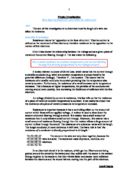
My graph shows that as the length of wire increases, the resistance increases.
The result for 100mm shows a mean resistance of 2.06 Ω and the result for 200mm shows 4.06 Ω. This shows a difference of approximately 2 Ω in 100mm of wire length. This pattern also continues throughout the rest of the graph, showing a proportional relationship between the variables.
The measured voltage of my circuit increased slightly each time the length increased, although the power pack showed the same voltage. This is because, with a short wire, some of the voltage is ‘used’ by the connecting wires. However, as the resisting wire gets longer, it needs more and more voltage to itself, so the voltage across the resisting wire becomes a higher proportion of the total voltage.
The current of my circuit decreased slightly each time the length increased. This is because current is like how much electricity is pushing through the circuit at a time. The resisting wire is like a smaller tunnel for the electrons to pass through. The means the electrons collide with each other more, transferring and therefore losing more of their own energy, so less electricity is passed through. The longer the wire, the more of a chance electrons have to collide and lose energy, so even less energy passes through the wire.
Evaluation
My ammeter and voltmeter were precise to 0.01 amps/volts. However, while measuring the values both ‘jumped’ a lot, meaning the readings I took were probably not as accurate as they would seem. To improve this, I would use a more accurate ammeter and voltmeter, as the ones provided by school were not very accurate and quite old. Alternatively, I could use an ohmmeter, which measures the resistance directly. This would reduce the problems in accuracy which come from having to use two separate machines to get one value.
My power pack was also quite inaccurate, as the voltage stated on the power pack was different to the voltage on the voltmeter. To improve this, I would use a power pack with a preset voltage, rather than adjustable. This sh9oulod mean the voltage was more accurate because there would be no possibility for the dial to be set or calibrated wrongly. This would improve the accuracy of my results.
In my method, the main inaccuracy was the length of the wire. This was due to two factors. Firstly, my measurement of the wire wasn’t very accurate, mainly because it was hard to straighten out the wire perfectly. It was also because I had three different samples of wire for each length, so they may have had slightly different length. To improve this, I could use straight pieces of wire instead of from a reel, and measure them against each other as well as the ruler. Alternatively, I could use a machine to cut the wire. Either of these would ensure that all three measurements were the same, and as accurate as possible. The second main inaccuracy was that, when I clipped my wire into the circuit, the crocodile clips might not have been at the very end of the wire. This could mean the measured lengths of wire were not quite the same as the length actually used in the circuit. To improve this, I would cut each length of wire slightly longer than needed, and then mark to show the length, so the crocodile clips could be placed on at exactly the right length.
Most of my error bars are fairly small, however the error bar for 400mm is very large, and the error bar for 500mm is also quite large. These differences occurred towards the end of my experiment, and so a possible explanation could be the connecting wires in the circuit were heating up due to prolonged use. Nichrome wire is more resisting than copper wire, which means it would have heated up more after the same amount of use. However, the increase in temperature would cause the wires to expand fractionally, which would lower the resistance. This variability could have been what made my later error bars larger than the earlier ones.
Another possible explanation for the large error bars could be human error. As I neared the end of the experiment, me and my team may have rushed the setup and measurements more, meaning less accurate results. To improve this, I would take the measurements spread out, ie 100, 200, 300, 400, 500 rather than 100, 100, 100, 200, 200, 200 and so on. This would mean any human error was spread more over different results, and would affect overall accuracy less.
Overall, I am fairly confident in my conclusion, as my graph has a very straight line of best fit, and the smaller error bars still support the line, as do the means of the larger error bars. Most of the possible improvements to my method and equipment are unlikely to be available in my school environment, and so I believe my conclusion is as accurate as I could reasonably make it.