Another factor which can be changed to affect the resistance is the length of the wire. The longer the wire is, the more the electrons in the wire collide with the fixed atoms in the wire, which increases the resistance because the fixed atoms block the electrons, making it harder for them to travel round in the circuit. We can test this factor because we can manipulate the length of the wire using crocodile clips. However one problem with testing this factor is that we cannot guarantee that the wire will be the same thickness all the way through the wire and one factor that we must keep the same is the diameter of the wire. A way that we could check that the wire has the same diameter all the way through it is by using a micrometer and using it to measure five points on the wire.
I have decided that the factor I will be investigation will be how the length of a wire affects the resistance.
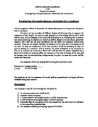
Preliminary
During my preliminary work, I had to decide on an operating voltage so I tested different voltages on different wire thicknesses. Firstly, I tested two voltages on the thinnest wire, which was 0.16 mm. I couldn’t record the data for 6 volts because the current would have gone to high and possibly damaged the wire.
Key: Outlier
We then tested the two voltages on the thickest wire, which was 0.40 mm.
I found that the voltages of 2V and 4V both caused the current of the wire to go above 1 Amp. The current cannot be allowed to go above 1A because if it went above it, it would cause the wire to heat up and eventually start glowing or burning, which would damage the wire. As well as this, there was one outlier in the data, which may have been caused by the ammeter being read wrongly since the current value in the first table for 40cm with the power pack set to 2V, was much lower than the other values. So I had to test the two other thicknesses of wire, 0.25 mm and 0.31 mm with the results in the table below.
In conclusion I have decided that, the operating voltage I will be working with during my experiment will be at 2 volts. This is because in my preliminary work, I have found that this voltage does not cause the current to increase above 1A. This is important since an increase above 1A because the temperature of the wire increasing may cause it to melt or break. As well as this, temperature is one variable we must try to keep the same so that our results are not affected by it. I cannot choose 1 volt as the operating voltage because when we tested different lengths of wire with that voltage, we found that the results didn't vary by a noticeable amount and this would consequently make it hard to draw a conclusion for the investigation using that data.
The lengths I have chosen for my investigation are 20-100cm with intervals of ten centimetres. These lengths were chosen because when tested with my operating voltage of 2V, they were the lengths which did not make the current go above 1A, though the current result for 10cm was 1.53 which went above 1A. The diameter of wire I will be using is 0.25 mm because when we experimented with different thicknesses of wire, we found that 0.25mm gave us results which did not go above 1A. The equipment I will need for the investigation is as follows:
- A wire board with Constantan wire attached
- A Voltmeter
- Ammeter
- Crocodile clips
- Power pack
- Wires for the circuit
The independent variable I will be changing is the length of the wire. The dependent variable is the resistance of the wire and the variable we would need to control would be the temperature because temperature would affect the results of my investigation.
The wires will be used for the circuit and the crocodile clips will be used to attach the circuit wires to the Constantan wire and also to change the length of the wire by using the wire board ruler to move the crocodile clips up and down the wire. The ammeter will be used to measure the current and the voltmeter to measure the voltage. A multimeter can be used to measure the resistance, however we found through our preliminary work that the multimeter only calculates resistance to one decimal place and so isn't as accurate as it can be. That is why I will calculate the resistance by using the results obtained for the current and voltage and Ohm's law by dividing the voltage by the current to work out the resistance. This is much more accurate than using a multimeter because the ammeter and the voltmeter work out current and voltage to two decimal places, meaning that our resistance will be more accurate as it to will be worked out to two decimal places.
To make sure that the controls I will put on the investigation to make sure the test is as precise as it can be and the results are reliable and accurate, I will make sure that the material of the wire used each time is kept the same by using the same wire board for the whole main investigation so the material doesn't affect the results I get. I will also make sure to keep the current of the circuit below 1A and the diameter of the wire the same for each test.
Finally, to make sure the results I get are reliable, I will make sure to test the voltage and current for each length of wire at least three times. I will then add the three results together and divide them by three so that I can get an average result for each length I test.
Before I carry out my main investigation, I decided to carry out a ‘test' investigation, using the lengths, the thickness and the voltage that I have chosen for the investigation. I did this so that I can be sure that the diameter, lengths and voltage are the ones I want to be using in the main investigation and that at no point does the current exceed 1A. Using my test investigation, I was able to re-evaluate the measurements I was going to use in my main investigation and through this, I decided that I would use wire with the diameter of 0.25mm because I felt it would give me better results.
Main Investigation
Key:
Variable resistor (the
Constantan wire)
Ammeter
Voltmeter
Power Pack
This is the method for my main investigation:
- Set up a series circuit around the wire board, which is shown above, and connect the ammeter in series and voltage in parallel. The voltmeter has to be connected in parallel, or otherwise it will not work at all.
- Connect the whole circuit to the power pack with the voltage I had chosen from my preliminary work, which is 2V.
- Before I turn on my power source, measure at five points along the wire, its thickness with a micrometer and calculate an average thickness. This is so that my test is more precise, as I’m not assuming that the wire is the exact thickness stated by its manufacturer.
- Connect the crocodile clip to the first length, which I will do by going along the metre ruler attached to the wire board, finding the length and connected the crocodile clip as near to it as possible. Then turn on the power source.
- Measure the current and voltage and record it down. I will need these values to work out resistance using ohm’s law.
- Turn of the power source, move the crocodile clip to the next length and turn it on again. This is so that the wire can cool down and temperature will have less of an effect on my results.
- Measure current and voltage again.
- Measure the voltage and current of the rest of the length, recording the figures as I go along.
- Repeat measuring voltage and current for each length, three times so I can compile an average. This will increase the accuracy of the data because the more times I repeat the test, the more accurate the results will be.
- When I finish measuring all the lengths, use my three sets of results to calculate the resistance of each length.
I decided to change my lengths from 20cm-100cm, to 10-100cm because it gave me a slightly wider range of data. When I tried the length 10cm again, the current did not go above 1A; the earlier result had been caused by systematic errors in the equipment because of the preliminary being carried out over several days, so the equipment I used would have changed. However, I will collect all the results for my main investigation in one day so that my results will not be affected due to equipment changes.
Equipment:
- Wire board with 0.25mm Constantan wire attached
- Voltmeter
- Ammeter
- Wires for the circuit
- Power Pack
- Micrometer for measuring wire thickness
The variables:
The independent variable is the wire lengths and the dependent variable material and temperature of the wire. I cannot keep the temperature of the wire the same exactly because the wire heats up anyway as the current run through it, due to the electrons colliding against the metal. But I can be able to control it as much as I was able to by keeping the current below 1A and by turning off the power pack after testing each length.
I have also tested each length of the wire three times so that I have a fair test and my results are more reliable as I will be taking an average from them. After I recorded the results in tables, I then found figures for the average resistance, which will be used in a graph.
As mentioned in my method, I decided to measure the thickness of my wire at five points using a micrometer. The reason for doing this is so that I could see if the wire was of a uniform width throughout it and also calculate an average width.
These results show that the thickness of a wire varies throughout the length of it and the diameters aren’t always the same. My average diameter was 0.23mm, which however is not 0.25mm, the diameter of wire the manufacturer states. This may have an effect on the results I record for my investigation, because as I have stated before, diameter does have an effect on resistance, with a wider diameter reduced resistance due to there being more space for the electron to move around. Since my diameter is smaller than it should be, the resistance values I record may be higher than they should be.
Conclusion
The graph on the previous page shows the length plotted against the average I calculated for the resistance. Firstly, the line of best fit shows that there is positive correlation, as the length increases so does the resistance. I decided to make some predictions about my data using my line of best fit. For example, I chose the lengths 30cm and 60cm and found the resistance.
Length 30cm Resistance 3.5 Ω
Length 60cm Resistance 7.1 Ω
The resistance for 60cm was almost double that of the resistance for 30cm, in fact the percentage increase for the two values was around 102.9%. This result shows that resistance and length must be proportional to each other, since as the resistance increased by the same amount that the length did. From this, I predict that if I for example multiplied a chosen length by 3, then the resistance of that length would be 3 times larger than the chosen length.
In order to determine the relationship between the two variables, I had to find out five gradients (shown below), which will hopefully help me establish a pattern between length and resistance.
Firstly, I have used the results I gathered from my main investigation to calculate the gradient of them.
I can see from these results that all the percentage increases are around that of a hundred percent. From this, I can make the assumption that as you increase the length of the wire, for example twofold, then the resistance of the new figure would be double the resistance of the number before. This means that resistance may be proportional to current. Though my values are definitely not accurate, since the increases are all different percentages, they are very reliable as the range between them is 4, which is small. To prove this hypothesis, I will also take figure from my graph, using my line of best fit and then I will also make some predictions and use my graph to see if they are correct.
Once again, my results are all reasonably close to a hundred percent. However, this time the range between them is about 13, which is larger than the range I got using my actual results. This implies that my line of best fit is not very accurate, though it is reliable. It may not be possible to make my line of best fit anymore accurate because its purpose is to show the general trend of data and it cannot fit to each result exactly. I will now predict some my data, following on with the idea that resistance must be proportional to length.
Length 12 cm Resistance 1.4Ω
From this length, I make the prediction that the resistance value for 24 cm, will be around 2.8Ω.
Length 24cm Resistance 2.7Ω
Percentage increase= 92.9%
Length 8 cm Resistance 0.8Ω
From this length, I make the prediction that the resistance value for 16 cm, will be around 1.6Ω.
Length 16 Resistance 1.8Ω
Percentage increase= 125%
Length 36 cm Resistance 4.2
From this length, I make the prediction that the resistance value for 72 cm, will be around 8.4Ω.
Length 72 Resistance 8.9
Percentage Increase= 111.9%
Once again, the results I have obtained from the graph prove the relationship between resistance and length. However, though my results seem to be reliable, I feel that my line of best fit is not as accurate as it should be and this could be what is making my percentage increases deviate so much from a hundred percent. I am particularly not happy with the result where I got 125% as that is a lot higher than the rest of the values I obtained.
Finally, I can also prove that resistance is proportional to length through the formula with R being resistance, ρ being resistivity, L equalling to length and A equalling to area. In the equation, ρ is constant, since in this investigation I am keeping the material of the wire the same and resistivity changes depending on the material and purity of the metal wire. This means I can remove it from the equation, which therefore equals. Then we have the inclusion of area in the formula, which is also constant. This is because, since I am investigating length, the area of the wire is the control factor I need to keep the same. This means I can also remove area from the equation which therefore becomes or more rightly, resistance is proportional to length.
As this diagram shows, an electrical wire is filled with negative electrical charges, which are called electrons. When an electrical circuit is switched on, the power source pushes the electrons around the circuit. As these charges flow through the wire, they also continually collide with the fixed lattice of atoms that are present in the wire, this creates resistance. The longer the wire is, not only do the electrons have longer to flow through the wire, there are also more collisions there would be between the electrons and the atoms. The result is that resistance increases, so if the length of wire doubles, then the resistance would increase twofold as well.
Evaluation
Resistivity
Resistance is a measurement that is dependent on the geometry of the wire, which is how long the wire is and how wide the diameter of the wire is. Resistance is defined by the formula:
R= Resistance, ρ= Resistivity, ℓ= Length of wire and A= Area of cross section
Resistivity is a material’s ability to transmit an electrical current and unlike resistance, () is independent of the geometrical factors and is defined by the formula:
To check whether my results are accurate and reliable, I will measure the resistivity of the Constantan wire using my results table. I will then compare my results to the known resistivity of the wire, to see if my results are close enough or have been influenced by other factors.
The resistivity of constantan wire is actually 4.9 x10⁻⁹, which means that though my results weren’t that far off, they were not accurate. Some outliers have appeared in these results. These outliers may have occurred due to systematic error which may have been caused by the equipment. For example, the thicknesses within my wire varied, which may have affected resistance. As well as this, another factor that could have affected my values is temperature, as I could not control it (the wire heats up as current passes through it), it would also affect my resistance values.
My resistance values were reliable since they were relatively close together and there was not a large amount of variance between them, shown by many of the range bars on the graphs being extremely close together. However there was one result with quite a large range. This could have happened because human error. It could also be due to me getting the readings wrong, because the voltage values kept fluctuating so I could not get a true value since the values did not stabilise.
In the equation , ρ is constant, which means that resistance is actually proportional to length/area. This can be proved by placing values into the equation. So for the length 40cm (5.73 x10⁻⁹) x = 4.68Ω
For the length 80cm (5.70x10⁻⁹) x = 9.31Ω
The percentage increase between 40cm and 80cm is 98.9%. By the value, therefore resistance must be proportional to length because the increase was nearly 100% with just a 1.1% error. The error was not human error but systematic error caused by the equipment. This is because, when I was recording my values, I had no time to wait for the voltage and ammeter readings to stop fluctuating, so I just wrote down the values as soon as they came up. These values may not have been the true values for voltage and current.
During this investigation, I measured the resistance using Ohm’s law instead of a multimeter, because the multimeter could only measure resistance to one decimal place, whiles using Ohm’s law would allow me to go to two decimal places, therefore Ohm’s law was much more accurate.
To keep my results more accurate, I had to keep the temperature constant. I did this by keeping current above 1A, because if it went above 1A then the wire would heat up and affect my resistance values. However, I could change the temperature itself directly due to lack of specialist equipment. To improve this in my next investigation, I could switch of the power source and wait a specified amount after measuring each length, so that the wire would be kept at a more stable temperature since it would be able to cool down. Temperature is one of the factors that I listed the beginning of my coursework, which affects resistance as it causes the electrons in the wire to speed up and collide more with the wire walls, ultimately increasing resistance.
I measured the thicknesses in the wire at five different points to calculate an average, however I found that the average thickness of the wire was smaller than the thickness the wire was supposed to be. This might have affected the reliability of the results since the smaller the diameter of the wire, the more resistance there is as the electrons have less space to move through the wire. Using a micrometer to measure the thickness was also more accurate because by knowing exactly how thick the wire is, I can then take into account the impact the thickness could have on my results. However, I cannot be sure that the average thickness I calculated may have been less precise than it could have been since I only chose five points, some of which were quite close together. A way I could make my average thickness more precise for my next investigation would be to measure more thicknesses on the wire, measuring ten points for example and I could also create equal spaces between each point so that a lot of the points do not end collecting together in one place.
I also chose a range of ten lengths from 10-100cm. Doing this increased reliability, because I had a wider range of data it was easier to recognise the way the data trended and also easier to recognise outliers in my results. Since the data also went up in regular intervals, it was much easier to work out the proportion of length to resistance than if the lengths went up in non uniform intervals.
I think that the improvements to be made for next time are, firstly to allow more time for the ammeter and especially the voltmeter readings to become more stable. I could do this by waiting a specified amount of time for each reading so that my test is fairer (I am waiting the same amount of time for each reading) and my results are more accurate due to them being less influenced by fluctuating voltage readings.
Another way I could improve my investigation would be to have a more accurate way of attaching the crocodile clips to each length of the wire. With the current method I use, the crocodile clips end up not being on the right length because the lengths are marked out on a metre ruler next to the wire. There is a bit of distance between them and because it is not possible for me to move the crocodile clip in a straight line, the results for the lengths were not accurate. To improve this method, I could either mark the lengths on the wire itself or instead use a ruler I can move up to the wire to make my lengths more accurate and precise. Another way I could increase the precision of my results is to use smaller crocodile clips as they take up less space and this would make it a lot easier to place them more accurately to the lengths I’m using. Changing the crocodile clip size and placement method is important because since length has an impact on resistance, I could be collecting inaccurate data for my investigation.
Finally, it is not just the constantan wire I was using that provided resistance. There was also some resistance in the other components, for example the connecting wires, the ammeter and the voltmeter. They provide resistance as the electrical current has to flow through all of them, though the resistance may not be of a very large amount. This is called contact resistance and its impact on my results is unavoidable, therefore there is nothing I can do to decrease this effect.
In my graph, most of my ranges were relatively close together, though the range I got for the length of 100cm, seemed too long compared to the other ranges. This may have been due to human error, for example not waiting for fluctuation in the recording equipment to stop. Also I may have attached the crocodile clips to the wrong place, which may have affected my results. This showed the reliability of my data and also showed it was quite precise. The range bars also did not overlap, which showed that there was a different 'true' value of resistance for each length. I also feel that my results were reliable because the points were either very close to or on the line of best fit. There were no outliers and the scatter moved upwards in a positive correlation. As well as this, the scatters in my graph were all relatively close together and the gaps between each point were around the same amount. However, though my points were very close to my line of best fit, I do not think it was drawn very well due to the percentage increases I calculated earlier were not as accurate as I thought they would be. As well as this, even though I did not identify any outliers in my results, there may have been outliers I missed because I did not scrutinise my data enough.
Though I do not think my results were very accurate, they were very reliable and precise because of the reasons stated above.
I took readings from an ammeter and a voltmeter. I intended to wait for each reading to stop fluctuating so that my results could be made more accurate but I did not have enough time so I did not do that. This may have made my results more accurate as I might not have recorded the true values for current and voltage since I ended up recording the first number I saw. This could have lessened the credibility of my conclusion, if the values I ended up using were not correct then the theory of length being proportional to resistance that I sought to prove with my data may be wrong. This decreases my confidence with my conclusion, however because most of my data followed a clear trend and I was able to reach my conclusion using a variety of methods to check it, I cannot readily discount my the validity of my conclusion.
Another reason why I’m less confident with my conclusion than I should be is due to the ranges of lengths I have chosen. Though going up in tens is a reasonable amount, I feel that my results could have gotten a much better accuracy by using smaller lengths. For example, I could have gone up in fives instead and ended up using twenty lengths instead of ten. To improve my conclusion next time, I must first increase the precision of the way I collect my data so that my results will be more accurate. I would also have to research more into resistivity and resistance, so that I could better use science to evaluate my data and write a better conclusion.