The resistance of a length of wire is calculated by measuring the current present in the circuit (in series) and the voltage across the wire (in parallel). These measurements are then applied to this formula:
R=V/I
Where V = Voltage, I = Current and R = Resistance
Electricity is conducted through a conductor, in this case wire, by means of electrons. The number of electrons depends on the material and more electrons means a better conductor, i.e. it has less resistance. The electrons are given energy and as a result move and collide with neighbouring electrons. This happens across the length of the wire and electricity is conducted. Resistance is the result of energy loss as heat. It involves collisions between the electrons and the fixed particles of the metal, other electrons and impurities. These collisions convert some of the energy that the electrons are carrying into heat.
For example, if there is water pipe where the water is the electricity, the water is the electric current and the pump is the battery. In the water pipe there is a part where the pipe is narrow less water will be able to get through that part of the pipe. So the water is restricted and this is exactly the same as the wire where the resistance will restrict the current.
Plan
Before we started our experiment we did some preliminary work in order to find a safe current to work at, because resistance is temperature dependant.
Equipment list:
- Power Supply
- Potential Divider
- Ammeter
- Voltmeter
- Set of Wires
- Wire (testing wire)
- Ruler
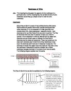
- Arrange apparatus as shown in the Diagram.
- Attach the wire to the crocodile-clips.
- Attach the wire at 10cm, 20cm, 30cm, 40cm, 50cm, 60cm, 70cm, 80cm, 90cm, and 100cm.
- Set the current using the variable resistor to the currents required.
- Take the reading from the voltmeter and record in results table.
- Repeat 3 times for each length of wire.
- Then work out the resistance using the formula V÷I=R (Voltage ÷ Current = Resistance)
- Do the same for different type of wires and plot on a graph.
There were 3 types accuracy equipment we used:
- Ruler – which was accurate to + or – 1mm
- Ammeter – which was accurate to + or – 0.01 amps
- Voltmeter – which was accurate to + or – 0.01 volts
To make sure our results were fair we did each result 3 times, worked out a resistance and then worked out the final resistance.
Making it Fair
We did certain things to keep the investigation fair:
- We used the same lengths of wire each time.
- We used the same current each time.
- We used the same material each time.
Safety
To make our investigation as safe as possible, we tried work in a safe and tidy environment which was not overcrowded. We also worked with less than 1 amp because it might overheat and there would be a danger of burning. We switched off the power when we were changing the wires to avoid getting burned. We did not cut the wire from the reel to avoid getting cut.
Results
We have tested constantan in this investigation.
Conclusion
The results in all the tables show that the resistance increases each time the length of the wire is increased, as shown in all of the tables above.
The length of the wire affects the resistance of the wire because the number of atoms in the wire increases as the length of the wire increases. The resistance of a wire depends on the number of collisions the electrons have with the atoms of the material, so if there is a larger number of atoms there will be a larger number of collisions, which will increase the resistance of the wire.
Evaluation
After doing this experiment, I have come up with a reliable set of results.
Even though I have achieved a good set of results there are obviously going to be errors, which I have made that could affect the investigation. The errors that I came across were, the wire was very hard to get straight and had bends, the voltmeter was only accurate to two decimal places so the voltage was flickering which made it hard to tell what the exact number was. To make my accuracy better we could have done more than ten lengths, done each result more than three times, used ammeter and voltmeter sensor. We could also have used different cross sectional areas or use different materials.
I think my graph was good to look at but there are still one or two anomalous results which could have been caused by accuracy measuring instruments which we could have improved.
To support my conclusion I could do some extra work like testing more materials to see what other materials it would work with. We could test more length to see if the graph will rise in proportion or will there be a point where the graph will bend and the resistance will not go any higher.