This real-life practical setup propelled me to undertake an investigation - To study the variation in tension in the left segment of a relatively inelastic and an elastic string tied between two supports with: -
- The point of application of force
-
Length of the string tied between the supports.
The first part involves studying the variation in tension force exerted as force is applied on different points across the tied string. Also, as in suspension bridges, the weight is felt by the roadway which exerts a compression force in the pillars. This in turn pulls the cables tighter and keeping this factor in mind, the second part of my study is the variation in tension when different lengths of the same string are tied between two supports.
At the end of the study, the trend between tension in the left segment and point of application of force can be modeled by negative quadratic equations. This goes on to explain that tension increases till the maximum point and then starts decreasing. Also, as the length of the string tied between is increased, the tension in the string decreases.
The intrinsic property of strings, such as the extent of deformation when under force determines the tension which it experiences. This is indicated by the strain value which has been subsequently calculated for the two strings in question; an inelastic and a relatively elastic string. At the end of the study, the strain value is related to the observations leaving scope for predictions about the behavior of strings of different properties.
Experimental Design
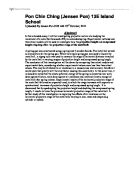
The practical application of my research question lies in suspension bridges and even guitar strings. However, for flexibility in my research and conforming to school laboratory apparatus, I have designed an experiment setup which comprises of a wooden board with a number of nails hammered from top to bottom on either side. Also, a grid was drawn on the board to easily make out the point of application of the force.
My preliminary view of the experiment comprised of two nails hammered into the wall. A string would then be attached between the two nails by tying the two ends of the string to the nails. However, the wooden board with a grid makes it easier to calculate and control variables. To keep a constant force, I chose to use a certain constant mass which would be tied to the string and whose position could easily be varied.
The point of application of force, that is, the horizontal distance from the rigid support is assigned the independent variable and the tension in the left segment becomes the dependent variable. Henceforth, all use of the word ‘tension’ would refer to tension in the left segment. The applied force is the controlled variable throughout the experiment. While comparing the variation of tension with the point of application of force in the two strings, the length of the string is also a controlled variable. However, the length of the string becomes an independent variable while studying the variation in tension with the length of the strings tied.
Controlling of Variables
- Applied Force
The force applied is required to be constant at all points of application to prevent disparity in the tension exerted. This is done by employing a uniform spherical bob of mass 69.3 gms.
Therefore, the force which is exerted in the form of the bob’s weight will be: -
F = ma
F = 0.0693 kg x 9.8 ms-2
= 0.679 N
- Length of the string
The length of the string is taken to be constant when varying the point of application of force. This is because the tension exerted varies when the length of the string is different (This is also another part of the study which is discussed later). To keep the length of the string constant, colored marks were made on the string and tied appropriately to the supports.
Firstly, at a length of string = 140 cm, data was collected for 10 points of application of forces. The force applied in the form of a spherical bob was movable and thus, the readings were taken starting close to the first rigid support and moving away such that by the time I reached the second rigid support, they were 10 points at which the vertical distance was measured. This was done for both the nylon string and the elastic band.
However, the experiment has another important observation attached to it, that is, to study the variation in tension with differing lengths of strings. Thus, 4 different lengths of the string which were greater than the least distance between the two nails (138 cm) were taken. I started with a length of 140 cm and measured the vertical distance for 10 points of application of force (horizontal distances). Then, the length of the string was increased by 4 cm and the vertical distance was measured for the same 10 points of application of force. The same was done for a length of string equal to 148 cm, and 152 cm. Both the elastic band and the nylon string followed the same procedures.
There were some initial obstacles which I came across but were overcome in due course. Firstly, I had planned to use a string of length equal to the distance between the two nails (i.e 138 cm). However, data collection became difficult for a relatively non-elastic string as the force applied could not produce an appreciable change in the vertical distance of the string. Thus, I modified my plans and used lengths which were greater than the actual distance between the two nails, that is, 140 cm, 144 cm, 148 cm, and 152 cm.
An ideal elastic string would be a one-piece rubber band. However, another issue was that I could not find a rubber band having a length of more than 1 m. Initially, I decided to join several rubber bands and assumed them to be acting as one string. But, this restricted the movement of the mass which acted as the force and also the properties of the joined rubber band varied due to the knots. Thus, I settled to use an elastic band similar to the kind used in garments.
Hypothesis
I predicted the end result of my experiment that as the distance from the rigid support increases, the tension force in that part of the string (irrespective of whether it is elastic or inelastic) which is tied to the corresponding rigid support, should increase. Therefore, I envisaged a linear curve. Also, I believed that the tension in the elastic string would be correspondingly less compared to the non-elastic string. For the second part of my observation, I expected the tension to be more when the length is relatively less, both for elastic and non-elastic string. Also, I had predicted that the tension be maximum at a point which was approximately half the distance between the rigid supports.
Experimental Procedure
Apparatus Utilized and their Specifications
- Plywood Board of dimensions 1.5 m x 1 m
- 18 nails (9 nails hammered vertically on either side at a vertical distance of 10 cm from each other and perpendicular horizontal distance of 138 cm)
- Nylon String (Length ≥ 1.6 m)
- Elastic Band (Length ≥ 1.6 m)
- String of negligible weight (50 cm)
- Uniform Circular Metal Bob (Mass – 69.3 gms)
- Wooden Ruler (1 m)
- Measuring Tape (1 m)
- Stools to balance the wooden board (2 nos.)
Procedure Followed
The procedure described here is for the relatively non-elastic nylon string. The same procedure is also adopted for the elastic band.
- Firstly, 140 cm of the nylon string was measured using a measuring tape and both ends were tied to the nails on either side.
- Next, a string of negligible weight was attached to the circular bob and tied to the nylon string. Thus, the nylon string became rigid.
- A horizontal distance of 9 cm from the nail on the left was measured using a ruler and the string attached to the bob was moved to exactly that point.
- As the bob acted like a force downwards, the vertical distance till the nails was measured using the ruler. This became the first reading.
- Steps 3 and 4 were followed for horizontal distances – 18 cm, 27 cm, 38.5 cm, 66.3 cm, 84.3 cm, 101 cm, 117 cm, 126 cm and 129.4 cm.
- The second part of the study involved varying the length of the string. Thus, the length of the string was increased by 4 cm so that it was 144 cm.
- Steps 2, 3, 4 and 5 were again followed.
- Readings were taken by increasing 4 cm each time such that the lengths of the string for which readings were taken were 140 cm, 144 cm, 148 cm and 152 cm.
Calculation of Tension
I have restricted myself to finding out the tension T1. As the system is in Static Equilibrium, the sum of all the vector forces must be equal to 0. There are three main forces acting on the system: - the weight of the bob, the tension T1 existing in the left part of the string and the tension T2 which exists in the right part of the string. The weight of the bob acts vertically downwards and the two tensions can be resolved into their horizontal and vertical components. The summation of all vertical forces, and also the horizontal forces . Using this property, the formula to calculate the tension T1 is found out to be
T1 =
Moreover, as we have taken y1 = y2
T1 =
For complete derivation of the tension T1, refer to Appendix 1.
Primary Data Collected and Tension Calculated
My data collection involves measuring the y1 distance for the corresponding application of force which is the horizontal distance from the first rigid support. Using the formula for Tension as derived in the last section, I have also calculated the tension T1 existing in the left part of the string.
Sample Calculation of Tension T1
When the length of the string = 140 cm and the point of application of force ‘x’ cm = 9 cm
T1 =
= = = 1.1863 ± 0.02 N
String Type 1: - Nylon String (Relatively inelastic)
String Type 2: - Elastic Band (Relatively Elastic)
Strain in the strings
To quantitatively draw a comparison between the elasticity of the two strings, it is better to calculate their strain values. This is done by taking a fixed length of both the strings and applying a constant force. The ratio of change in the length of the strings to the actual length indicates their responsiveness to force.
Strain, δ =
For this, a controlled initial length (44 cm) was taken for both the strings and also the same bob was employed as the constant force (0.679 N).
Nylon String Elastic Band
Initial Length = 44 cm Initial Length = 44 cm
Length after force applied = 49 cm Length after force applied = 54 cm
Change in length = 49 – 44 = 5 cm Change in length = 54 – 44 = 10 cm
δnylon = = 0.114 δband = = 0.227
Thus, the elasticity of the elastic band is almost twice that of the nylon string. These strain values shall be used in the analysis to analyze the reason for the variation in tension in the analysis.
Data Analysis
- To compare the tension in a nylon and elastic band with the point of application of force for a constant length of 140 cm
String Type: - Nylon String (Relatively Non Elastic)
As we move horizontally from left to right across the nylon string while applying force, the tension experienced is highest at a point which is approximately the mid-point of the distance between the two rigid supports (nails). From that point onwards, the tension starts decreasing. The minimum tension experienced will be at a point of application of force which is the farthest from the first rigid support. Hence, the curve is roughly like a wave which is extended towards the end.
String Type: - Elastic Band
Here we see that the tension is approximately the highest initially itself. From the first point of application onwards, there is a very slight increasing trend observed and the tension is highest at a point of application of force which is before the halfway distance between the rigid supports. From the maximum point onwards, the tension keeps on reducing and the minimum point lies when the point of application of force is the furthest from the first rigid support
Comparing the occurrence of the maximum tension in a nylon string and an elastic band
Both the nylon and the elastic band can be modeled by quadratic equations. This enables us to study the symmetry in the tension trend for the different strings.
Axis of Symmetry
The axis of symmetry of the above graph is an important indication of the trend in tension as it divides all tension values in two parts gives the point of application of force wherein the tension is expected to be maximum.
The general quadratic equation y = ax2 + bx + c
Axis of symmetry =
Nylon String Elastic Band
y = -2.413x2 + 3.099x + 0.952 y = -0.504x2 + 0.392x + 0.711
Axis of symmetry = Axis of symmetry =
Axis of symmetry = 0.6421 m Axis of symmetry = 0.3889 m
From the values calculated above, we can infer that for a relatively non-elastic string the tension force is maximum further away from the rigid support and occurs somewhat halfway the distance (d/2 = 0.69 m) between the two supports.
However, that is not the case with a relatively elastic string wherein the tension is maximum and the trend is symmetrical quite nearer to the rigid support.
- To study the variation in tension with different lengths of the string
String Type: - Nylon String
The graph makes it clear that as the length of the string tied between the two supports decreases, the tension values increases. It is not only the maximum tension, but in fact tension at all points of application of force is more when the length of the string is 140 cm. The tension starts decreasing with increasing length. However, the decrease in the tension values is not at all linear or equal. Rather, the area between the curve of 140 cm and 144 cm is larger compared to that between 144 cm and 148 cm. This indicates that the tension values decrease but not uniformly.
String Type: - Elastic Band
Due to the close proximity of the four series, it is difficult to display the polynomial equation on the graph. Here are the polynomial equations for all the four series: -
Although the trends in tension for an elastic band are also modeled by quadratic equations, however, it is not similar at all to the nylon string. Firstly, the maximum tension occurs closer to the rigid support as observed in Part 1 already. Secondly, the difference in the range of tension in the elastic band when taking different lengths is not much. This is the reason why the curves for all the four lengths are very close to each other unlike the nylon string.
Conclusion
- Variation in tension with point of application of force
My hypothesis of a linear increasing trend for both the strings was proved wrong by Graphs 1 and 2. For the inelastic string, it is in the form of a wave with the maximum tension occurring approximately halfway the distance between the two supports. However, the same is not reciprocated by the elastic band. Firstly, the magnitude and the range of the tension experienced is less compared to the inelastic string. This is because it has a higher strain value which means a greater amount of stretch compared to the inelastic string when the same force is applied. Thus, the same force is spread over a larger area in the elastic band compared to the nylon string. Secondly, the maximum tension occurs nearer to the rigid support as depicted by the axis of symmetry.
- Variation in tension with respect to length of the string used
Graph 4 and 5 both confirm my hypothesis that as the length of the string increases, the tension in the string decreases. We can come upon the inference that,
Tension in a non-elastic string α
However, the decrease in the tension is not uniform in case of the inelastic string. As the elasticity increases, the difference in tension due to length of the string is relatively less which is shown by the tension trend of the elastic string.
This happens because as the elasticity of the string increases, it stretches and therefore, the tension force is also spread about a wider area.
Relation of tension to the strain values of strings
The strain values have been calculated in the previous section and it is found out that δnylon < δband . By observing the changes in the trends of the two strings, it is possible to predict the tension behavior of strings having other δ values also. First, we shall take the change in the trend which takes place as we move from δnylon to δband (0.114 to 0.227)
Using the observations made earlier, it would be safe to assume that as the strain value increases, that is to say, the string becomes more elastic, the tension values decrease. This is shown as in the transition from graph 6 to graph 7. Also, along with the decrease in the tension values, the curve stretches out (depicted by graph 8), which indicates that the range of tension (maximum – minimum) decreases. Thus, we can go on to say that the tension for a highly elastic string (δ >0.227) would be expected to be roughly uniform irrespective of the point of application of force and the length of the string. Conversely, for strings which are highly inelastic (δ < 0.114) the range of tension values is expected to be high and also, there would be exponential increase in the tension values with reducing lengths of the strings.
Evaluation
Error Analysis
The systematic error in the experiment is very insignificant. The uncertainty values, compared to the tension calculated are very less which is also why they are not visible in the graphs as error bars. The uncertainty for the tension values calculated varies with every observation. The minimum uncertainty is ±0.001 N and the maximum is ± 0.05 N. Besides, there are some random errors in the designing of the experiment are as follows: -
- The spherical bob which was used as a constant force was not fully suspended in air. Some part of it rested on the wooden board which may have slightly reduced the effective weight of the bob and thus the force. What I have taken as force in my calculations may actually be a little greater than the actual force
- The elastic band was wider than the string with which the bob was tied. Thus, the elastic band became a little twisted at the point of application of force. Yet care was taken to try and measure the vertical distance as far as possible keeping the center point of the band as the reference point.
- The nylon string used was not straight but it tended to incur folds at certain points. Although it was kept under a force for quite some time so that it becomes uniform, yet all complete uniformity could not be achieved. This slight non-uniformity may have led to variation in the strain value of the string.
Acknowledgement
With the fulfillment of a project, especially when it is from deep within the heart reflecting the inner ambitions, there comes a joy unfathomable. Physics has and will always fascinate with its simple intricacies. To sustain my interest in the pursuit of physical knowledge, the extended essay being a part of that pursuit, there are a few people I would like to thank: -
- My Physics teacher and Extended Essay supervisor, Mr. Venkataragavaraj for being a mentor as well as the light to guide me on my way throughout my research and otherwise.
- The Lab Assistant, Mr. Sivakumar for his utter sincerity and dedication towards helping me out carry the research effectively.
- My will power, for I have considered it an entity henceforth, for keeping me going when things got tough.
Bibliography
Books Referred
-
Physics for Scientists and Engineers by Douglas Giancoli; Prentice Hall Publications
Third International Edition
Chapter 12, Page 300
- Advanced Physics by Tom Duncan and John Murray
Fifth International Edition
Websites Referred
-
Image 1. Severn Suspension Bridge taken from Accessed on 30th August 2007
-
Accessed on 15th May 2007
Appendix 1 – Calculation of Tension
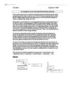
Figure 3 indicates that the bob is at a certain random distance ‘x cm’ from the point of suspension (nail) on the left. If the distance between the two point of suspensions on either sides is taken to be ‘l’, therefore the distance between the point of application of force and the point of suspension on the right would be ‘l – x ’.
We can see that due to the application of force, the string gets divided into two parts. The vertical distance to both the left and the right point of suspensions is assumed to be ‘y1 cm’ and ‘y2 cm’ respectively. If we assume a horizontal line to exist at the point of application of force, we can see that an angle is subtended at the point of application of force on both sides. The angle which is subtended by the string on the point of application of force to the point of suspension on the left is assumed to be ‘Ө1’ and to the point of suspension on the right is assumed to be ‘Ө2’. Finally, the Tension force exerted by the two parts of the string to their respective rigid supports is assumed to be ‘T1’ and ‘T2’, respectively.
Using all these variables and applying the conditions for Static Equilibrium, I have found a general formula as follows to calculate ‘T1’ and ‘T2’. The derivation of the formula is as follows: -
As the system is in equilibrium, the sum of all the vector forces acting must be equal to 0. In the system, there are three main forces which are acting: -
-
Tension, T1 in the part of the string tied to the point of suspension on the left
-
Tension, T2 in the part of the string tied to the point of suspension on the right
- Force acting downwards, which in this case, the weight ‘W’ of the bob
We shall resolve all the forces acting on the system into two parts and since the system is in equilibrium, the sum of all the forces in their respective components will also be 0: -
Σ F x = 0 (Sum of all horizontal forces is equal to 0)
Σ F y = 0 (Sum of all vertical forces is equal to 0)
It is also important to define the sign convention as we are dealing with a vector quantity (Force). The following figure gives the sign convention: -
Using the Cartesian plane, I have assigned the point of application of force as the point of origin. Therefore, all forces acting from the positive x and y direction shall be positive whereas those acting from the negative x and y direction shall be negative. To find out the formula, all the x forces are resolved as follows: -
As Σ F x = 0
-T1 cosӨ1 + T2cosӨ2 = 0
Substituting cosӨ1 = and cosӨ2 = above
-T1 + T2 = 0
T1 = T2 ---------------------------------------- (1)
As Σ F y = 0
T1 sinӨ1 + T2 sinӨ2 – W = 0
Substituting sinӨ1 = and sinӨ2 = above
T1 + T2 - W = 0 ---------------------------------------- (2)
Substituting the value for T2 in Equation (2) from Equation (1)
T1 + T1 - W = 0
T1 + T1 - W = 0
= W
Or, = W
= W
= W
Or, T1 = -------------------------- (3)
When y1 = y2
T1 = -------------------------- (4)
Appendix 2 – String Samples used
Candidate Name: Ladha, Sanchit
Candidate Session Number: 001070 - 006 Page