g = 9.81ms-2
3 Approach to solving problem
3.1 Assumptions
Ram operates in compression.
This is a valid assumption to make as the ram is constantly pushing against the force exerted by the load.
Masses of members in crane are negligible compared to load. This is justified as including these would make equation 7 invalid.
Any non-linear effects are neglected. Only forces in two dimensions are considered.
Members are infinitely strong. They do not deflect or buckle.
3.2 Flow chart and Methodology
The constants, rmin, rmax, M, L, Fmin and Fmax were initially defined. Fmin and Fmax were set to infinity and 0 respectively. The optimization process involved the creation of two loops. These were an outer loop which varied ϕ between 0⁰ to 180⁰ and an inner loop which varied θ between -20⁰ to 80⁰, each in steps of 1⁰ increments. The outer loop produced values of C2 and C1 which in turn were used to calculate a and b. This resulted in 181 values of a, b and ϕ, including complex numbers. By analysis of equation 4 these complex numbers were removed by setting the following condition:
if C1>C2 && C1>0 && C2>0
a = 1/2 * ( sqrt(C1 + C2) - sqrt(C1 - C2));
b = C2/(2*a);….
… end
This resulted in sixty six feasible values of a, b and ϕ, each of which were varied in the inner loop through θ. Each iteration calculated the length of the ram, r and the force in the ram, F. A table of forces was created for which the maximum, Fmax, was identified using the max() function to find the peak force for each iteration.
This inner loop resulted in a total of 101×66 values of F, one of which was the minimum peak force. Bearing in mind that Fmin and Fmax were initially set to infinity and 0, the following ‘if’ statement was made:
if Fmax < Fmin % selects optimum values
Fmin = Fmax;
…
This basically means that in the first iteration Fmax will be less than infinity therefore Fmin updates itself to the value of Fmax. If in the second iteration Fmax > Fmin, Fmin does not update itself. If Fmax < Fmin on the third iteration Fmin will update itself to that value of Fmax. The final value obtained from this is the minimum peak force. The corresponding optimal values of OA, OB and ϕ were simply obtained within the ‘if’ statement as such:
…
OA = a;
OB = b;
PHIopt=phi;
…end
The boom angle at which the peak force of the optimized crane occurs was found by creating a table of forces unique to the optimized design, with values of θ in the second column. The ‘find’ function was used to determine which row the peak force occurred. In the second column of that row, the corresponding value of θ was found, θpeak. This worked for any variation of the initial constraints in section 1.
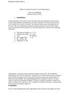
4. Results
The following results were obtained from the optimization routine by using increments of 1⁰ for θ and ϕ. Figure 2 shows geometry of optimized crane sketched using Solid Edge®. Dimensions are in millimetres.
Table 1
4.1 Evaluation of results
The graph shows the variation of force with the boom angle (theta) of the optimized crane. The force peaks at 222639N at 23⁰ above the horizontal, and declines to a minimum at 80⁰ above the horizontal. These results were calculated using a 1⁰ increment for ϕ and θ. The accuracy of this can however be questioned. This is treated in section 5.
5 Accuracy of results
To give a good idea of the accuracy of the final results, different increments, larger and smaller were entered into the GUI to produce the results seen in tables 2 and 3.
The largest entered was 20⁰ and the smallest, 0.1⁰. The results from 0.1⁰ are assumed to be the absolute values of peak force, OA and OB. This is because the most iterations are executed in generating these, hence they are the most accurate. The results from larger increments are less accurate as less iterations are made to generate them. This enables the calculation of the accuracy of the results from larger increments relative to those of 0.1⁰.
5.1 Accuracy of Peak Forces:
Table 2
Analysis of Peak Force accuracies
Rather than using percentages, the accuracies of these were measured by calculating actual difference between the forces from the larger increments and that of 0.1⁰. Percentage values would be too small and would give the misleading notion that the differences in forces are negligible.
Increments of 20⁰ showed an over-estimate of 6614N. Increments of 10⁰ showed an under-estimate of 158 N. Increments of 5⁰ showed an under-estimate of 40N.
Increments of 1⁰ showed an over-estimate of 9N and 0.5⁰ an under-estimate of 1N.
This shows that using a 1⁰ provides an accurate enough estimate of the peak force.
5.2 Accuracy of OB, OA :
Table 3
Analysis of accuracies of OB and OA
For the lengths OB and OA, the percentage difference between the results from larger increments and 0.1⁰ were used to estimate their accuracy. This is because their actual differences, in metres are so small. Using percentages makes their differences easier to quantify.
OB
An increment of 20⁰ produced an over-estimate of roughly 18% in relation to 0.1⁰ increments. Increments of 10⁰, 5⁰, 1⁰, produce over-estimates of 0.41% and with 0.5⁰ an under-estimate of 0.14%.
OA
The percentage difference calculated for a 20⁰ increment shows, roughly an 11% under-estimate, for 10⁰, 5⁰ and 1⁰ an underestimate of 0.33% is produced. With 0.5⁰ an overestimate of 0.7% is produced.
Again, due to the very small percentage difference between 1⁰ and 0.1⁰ for OA and OB,
It can be concluded that 1⁰ provides an accurate enough estimate for OB and OA.
Overall Evaluation of Accuracies
The accuracies estimated use the assumption that the results from 0.1⁰ are the absolute values of peak force, OB and OA, as they are the most accurate. However, the ‘absolute’ values could be defined using an even smaller increment eg 0.01⁰. Though this would provide a very high degree of accuracy, processing this in Matlab® would be slow. Designing and building the ram component to that degree of accuracy would also be impractical as it would require extremely precise engineering, which would be costly. For the sake of practicality a good enough estimate for the increment must be decided upon using good engineering judgement. In this case 1⁰ was decided upon for the final result.
6 Conclusions
The final results in 4.1 were obtained using a 1⁰ increment for ϕ and θ. This could have been made more accurate by using smaller increments such as 0.5⁰ or 0.1⁰. However, such small increments slowed down operation of the MATLAB® script. Therefore an increment of 1⁰ had to be settled upon. This problem could have been overcome in the programming by avoiding the use of loops altogether, and rather using matrix and vector manipulation. This uses much less memory hence allows the programme to operate more efficiently, even with smaller increments. This optimization process could have been further refined by including materials for the crane. This could give a realistic idea of how much load the boom and the ram could bare before failure. This would also enable the inclusion of a safety factor into the calculations for the peak force of the ram. Including the masses of the members and their material would also give an indication of cost which must be minimized.
7 References
Title: MATLAB GUI Tutorial for Beginners
Author: Quan Quach
Date created: 23/10/2007
URL:
Date visited: 12/11/11 13:00
This website provided tutoring on how to create a GUI. The code from the ‘my-adder’ script was adapted the suit the GUI created.
Title: Truss Analysis
Author: Hossein Rahami
Date created: 17/03/07
URL:
Date visited: 28/11/11
This website provided the coding meant for truss analysis and plotting these trusses.
The code was adjusted to plot the crane geometry in the GUI.
Title: How to create an error message for a GUI?
Author: Stefan Heinen
Date Created: 8/02/11
URL:
Date visited: 30/11/11
This website provided the code to show an error messages.
Title: Computing Assignment: Crane Design
Author: John Chick
Organisation: The University Of Edinburgh
Date published: 29/09/11
8 APPENDIX
Sample GUI output
MATLAB® SCRIPT
% crane_design.m
% script to optimize crane
% Arelo Tanoh
clc; clear all
% variable dictionary
% rmax extended ram length (m)
% rmin retracted ram length (m)
% theta_min minimum boom angle (degrees)
% theta_max maximum boom angle (degrees)
% L Boom Length (m)
% M Load (Kg)
% Fmin Minimum Ram Force (N)
% Fmax Maximum Ram Force (N)
% k,l loop counters
% C1,C2 Parameters for finding a & b
% a OA (m)
% phi Angle between OA and horizontal axis (degrees)
% gamma Angle BOC (degrees)
% b OB (m)
% define variables
rmax = 2.2;
rmin = 1.2;
theta_min=-20;
theta_max=80 ;
alpha = 20;
L =4;
M = 4000;
% set minimum Force to infinity
Fmin=inf;
% set maximum Force to zero
Fmax =0;
% Optimization
k =1;
% vary phi
for phi=[0:1:180]
gamma=alpha+phi;
% calculate C2
C2 = ( rmax^2 - rmin^2)/(cosd(gamma+theta_min) - cosd(gamma+theta_max));
% Calculate C1
C1 = rmax^2 + C2*cosd(gamma + theta_max);
% Show table of C1 and C2 values
tableC1C2(k,:) = [ k C1 C2 phi ];
% remove any imaginary numbers generated
if C1>C2 && C1>0 && C2>0
% calculate a
a = 1/2 * ( sqrt(C1 + C2) - sqrt(C1 - C2));
% calculate b
b = C2/(2*a);
% show how a and b vary with phi
tableABphi(k,:) = [ k a b phi];
l =1;
for theta = [theta_min:1:theta_max]
% calculate ram length
r = sqrt((a^2 +b^2) - 2*a*b*cosd(theta + gamma));
% calculate Force of ram
F = (r*M*9.81*L*cosd(theta))/(b*a*sind(theta + gamma));
% show all values of r in table
tableR(l,:)=[r];
% show all values of in table
tableF(l,:)=[F];
% show all values of theta in table
tabletheta(l,:)=[theta];
% maximum value of f in table above
Fmax = max(tableF);
% table of F ans theta values
table_F_theta(l,:)=[F theta];
l= l+1;
end
if Fmax < Fmin
% Condition constantly updates until minimum peak force found
Fmin = Fmax;
% shows optimized OA
OA = a;
% shows optimized OB
OB = b;
% shows optimized phi
PHIopt=phi;
% generates table of phi and theta
tableF_theta_opt = [table_F_theta];
% locates angle on optimized crane at which peak force occurs
[row , col] = find(tableF_theta_opt==Fmin);
theta_Peak = tableF_theta_opt(row,2); % value of angle at which peak force occurs on crane
end
tableAllF(k,:)=tableF; % Matrix showing all values of F generated with
% each iteration
end
k = k+1;
end
Fpeak = Fmin;
% Plot graph
% Values Of forces in optimized crane
F_opt = tableF_theta_opt(:,1);
thetaPeak = theta_Peak;
theta_opt=tableF_theta_opt(:,2);
plot(theta_opt,F_opt),xlabel('Boom angle (degrees)'),ylabel('Force in ram (Newtons)'),title('Ram Force V Boom Angle'),grid on;
% display results
% sprintf function rounds values to 0 decimal places
disp([' Phi Optimum : ' , sprintf('%5.0f',(PHIopt)),' degrees ']);
% sprintf function here rounds values to 0 decimal places
disp([' A Optimum : ' , sprintf('%5.3f',(OA)), ' metres']);
disp([' B Optimum : ' , sprintf('%5.3f',(OB)), ' metres']);
disp([' Peak force: ' ,sprintf('%5.0f',(Fpeak)), ' Newtons']);
disp([' Angle of Peak force:', num2str(thetaPeak),' degrees ']);