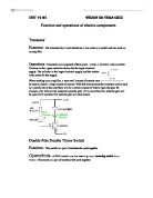
Output of the Schmitt trigger is connected to the base of a PNP transistor driving it to cut off thereby cutting off current and making the relay contacts remain open.
Ac to Dc converter:
A power supply is a device that supplies to one or more . The term is most commonly applied to devices that convert one form of electrical energy to another, though it may also refer to devices that convert another form of energy (e.g., mechanical, chemical, solar) to electrical energy. A is one that controls the output voltage or current to a specific value; the controlled value is held nearly constant despite variations in either load current or the voltage supplied by the power supply's energy source.
Every power supply must obtain the energy it supplies to its load, as well as any energy it consumes while performing that task, from an energy source. Depending on its design, a power supply may obtain energy from
-
The amount of and it can supply to its load.
- How stable its output voltage or current is under varying line and load conditions.
- How long it can supply energy without refueling or recharging (applies to power supplies that employ portable energy sources).
VOLTAGE COMPARATORS
A voltage comparator is a device used to compare two voltage levels. The output of the comparator will show which of the outputs is larger. Therefore it acts as a switching device, producing a high output when one input is larger than the other and switching to a low output if the other input becomes larger.
An operational amplifier is used as a voltage comparator by operating with no feedback and by connecting two voltages to be compared to the inverting and non inverting inputs. The amplifier output is driven to one of its output voltage limits when there is a very small difference between its input levels due to a very large open loop gain.
Properties of operational amplifiers are;
- Infinite input impedance
- Zero output impedance
- Infinite voltage gain
- Infinite bandwidth
- Characteristics that do not change with temperatures
Uses of op amps
- Scale changing
- Analog computer operations
- Instrumentation and Control systems
- In phase and oscillator circuits
RELAYS
A relay is a device consisting of a coil wound on soft iron core. It is an electrically operated switch. When current flows through the coil of the relay, a magnetic field is set up which attracts the iron arm of the armature of the core of the magnet.
The set of contacts of the armature and relay frame close completing a circuit across its terminals. When the magnet is de-energized, the return spring returns the armature to the open position and the contacts open breaking the circuit across the terminals.
The coil current can be on or off so relays have to switch and they are double throw or change over switches. Relays allow one circuit to switch a second circuit which can be completely separate from the first.
Current flowing through the relay coil creates a magnetic field that suddenly collapses when the current is switched off. The sudden collapse of the magnetic field causes or induces a brief high voltage across the relay coil. These high voltage spikes can destroy transistors and ICs in the circuit.
To prevent damage a protection diode is connected across the relay coil. It allows the induced voltage to drive a brief current through the coil and diode so the magnetic field dies away quickly rather than instantly. This prevents the induced voltage from becoming high enough to cause damage to transistors and ICs.
Relay connections
Factors to consider while choosing a relay
1. Physical size and pin arrangement
2. Coil voltage i.e. the relays coil voltage rating and resistance must suit the circuit powering the relay coil.
3. Coil resistance – the circuit must be able to supply the current required by the relay coil.
4. Voltage and current switch ratings
5. Switch contact arrangement (SPDT, DPDT)
Advantages of relays
1) Relays can switch A.C. and D.C. while transistors can only switch D.C
2) Relays can switch high voltages while transistors can’t.
3) Relays are a better choice for switching large currents (>5A)
4) Relays can switch many contacts at once.
Disadvantages of relays
1) Relays are bulkier than transistors for switching small currents.
2) Relays cannot switch rapidly (except reed relays) but transistors can switch many
Times per second.
3) Relays use more power due to the current flowing through their coil.
4) Relays require more current than many ICs can provide, so a low power transistor may
be needed to switch the current for the relays coil.
Oscillator:
The 555 is configured in the standard astable oscillator circuit designed to give a square wave cycle at a period of around 1 cycle/sec. A potentiometer is included in the design so the period can be set to exactly 1 second by timing the LED flashes. A jumper connection is provided so the LED can be turned off. As soon as power is applied to the circuit counting begins. We have not reviewed the operation of the 555 IC here.
The output pulse from pin 3 of the 555 is fed to a the clock input pin 10 of the 14-stage binary ripple counter, the 4020 (or sometimes 14020.) You can see from the schematic that the LED input is taken directly from this connection.
Ripple Counter:
The counter output wanted is set by a jumper. Eleven counter outputs are available: 8 counts, 16 32 64 128 256 512 1024 4096 and 8192 counts. If the 555 is set to oscillate at exactly 1.0Hz by the on-board trim pot then the maximum timer interval which can be set is 8192 seconds (just over 2 hours.) At the end of the counting period a pulse is output on the pin with the jumper on it.
The 14020 ripple counter advances its count on each negative transition of the clock pulse from the 555. So for each output cycle of low-high-low-high the count is advanced by two. It can be set to an zero state (all outputs low) by a logic high applied to pin 11. In this circuit C3, R4 and D1 are arranged as a power-on reset. When power is applied to the circuit C3 is in a discharged state so pin 11 will be pulled high. C3 will quickly charge via R4 and the
Level at pin 11 falls thus enabling the counter. The 14020 then counts clock pulses until the selected counter output goes high. D1 provides a discharge path for C3 when the power is disconnected.
Transistor Switch:
The output from the 4020 goes to a transistor switch arrangement. We have wired two BC547 so that either switching option for the relay is available. A jumper sets the option.
The relay can turn ON when power and counting start then turn OFF after the count period, or it can do the opposite. The relay will turn ON after the end of the count period and stay on so long as power is supplied to the circuit.
Note that the reset pin of the 555 is connected to the collector of Q1. This enables the 555 during the counting period but as soon as Q1 is turned on the 555 is disabled as the collector of Q1 is pulled low. These kits are constructed on a single-sided, routed, FR4 fiber glass printed circuit board (PCB) with a printed overlay and bottom solder mask. Protel Autotrax and Schematic were used to produce them.
Seven-Segment Display
A seven-segment display (SSD), or seven-segment indicator, is a form of electronic for displaying that is an alternative to the more complex displays. Seven-segment displays are widely used in , electronic , and other electronic devices for displaying numerical information.
A seven segment display, as its name indicates, is composed of seven elements. Individually on or off, they can be combined to produce simplified representations of the . Often the seven segments are arranged in an (slanted) arrangement, which aids readability.
In most applications, the seven segments are of nearly uniform shape and size (usually elongated , though and can also be used), though in the case of , the vertical segments are longer and more oddly shaped at the ends in an effort to further enhance readability.
The seven segments are arranged as a of two vertical segments on each side with one horizontal segment on the top, middle, and bottom. Additionally, the seventh segment bisects the rectangle horizontally. There are also and (for full ); however, these have mostly been replaced by displays.
The segments of a 7-segment display are referred to by the letters A to G, as shown to the right, where the optional DP (an "eighth segment") is used for the display of non-integer numbers.
Power Supply:
Countdown Timer:
Conclusion: We have implemented the appropriate logic circuit for proper timer operation. We also have verified the theory presented. We have been familiarized with pin configurations and proper application of specific integrated circuits related to this project. We have also practiced troubleshooting logic circuits.
%%%%%%%%%%% THE END %%%%%%%%%%%