B - Yield Stress
The stress at which yielding occurs across the whole specimen. That is, this is the point where the materials’ deformation is no longer linear, i.e. no longer obeys Hooke’s Law. It corresponds to the onset of plastic deformation. In brittle materials and plastics, the point where the materials move away from linearly is often hard to define. In a brief, at this point, the deformation is purely plastic.
C – 0.1% Proof Stress
A third point is sometimes used to describe the yield stress of the material. This is the point at which the specimen has undergone certain (arbitrary) value of permanent strain, usually 0.1%. The stress at this point is then known as the 0.1% proof stress. This is used because the precise positions of A and B are often difficult to define, and depend to some extent on the accuracy of the testing machine.
D – Ultimate Tensile Strength (UTS)
The point at which plastic deformation becomes unstable and a narrow region (a neck) forms in the specimen. The UTS is the peak value of nominal stress during the test. Deformation will continue in the necked region until fracture occurs.
E – Final Instability Point
The points which fracture occur.
F – Fracture Stress
The stress which fractures occurs – only obtainable from the true stress-strain curve. It can be less than the UTS.
Experimental Arrangement
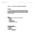
Apparatus
- Tensile testing machine
- Lindley extensometer
- Three different materials such as: Mild steel, Copper, and Duralumin
- Micrometer (to measure the diameters of the materials)
The Lindley extensometer was attached to the specimen and the specimen into the upper jaws of the testing machine. The zero of the load scale was adjusted as required and then the lower jaws of the testing machine were connected to the specimen. The extensometer was also checked if it was functioning by applying a small load.
Sequence of Operation
- The mean diameter of the specimen was estimated by not less than six micrometer screw gauge readings.
- The Lindley extensometer to the specimen was fixed as 1 division measured 0.001mm extension and 1 revolution measured 0.1mm extension
- The specimen into the upper jaws of the testing machine was inserted.
- The extensometer was secured.
- The zero of the load scale (as necessary) was adjusted.
- The lower jaws of the testing machine with the specimen were engaged.
- The extensometer was also checked if it was functioning by applying a small load.
- The test was being preceded methodically and unhurriedly until the specimen fractured.
Result
The readings taken for mild steel – Table 01
The data for the mild steel specimen:
Average diameter=10.097mm
Maximum Load = 8300 lb
Breaking Load = 5600 lb
Elongation = 64.0 mm – 50.0mm=14mm
% Elongation = 28%
% Reduction in Area = 69.11%
Minimum diameter at fracture = 5.613mm
The data for the copper specimen:
Average diameter=10.03mm
Maximum Load = 6500 lb
Breaking Load = 4000lb
Elongation = 58.0 mm – 50.0mm=8mm
% Elongation =16 %
% Reduction in Area = 72.27%
Minimum diameter at fracture = 5.28mm
The data for the duralumin specimen:
Average diameter=9.49mm
Maximum Load = 7770 lb
Breaking Load = 7100 lb
Elongation = 50.0 mm – 55.0mm
% Elongation =10 %
% Reduction in Area = 30.44%
Minimum diameter at fracture = 7.92
Discussion
From the data obtained for the materials tested it had been realized that the maximum load for steel and duralumin were about the same but the breaking loads were different. The steel had a lower breaking load than the duralumin, which was 5600 lb. it tells that steel has more ductility than the duralumin, which had a breaking load of 7100 lb. Also steel had a percentage elongation of 34% where duralumin only had 10% which also tells that steel is more ductile and the duralumin is more brittle. A gap gauge was used in the experiment to measure the minimum diameters. The steel rod had a smaller diameter at fracture of about 5.613 mm. While duralumin had a minimum diameter of about 7.92mm and it also had a 45˚ break, and that is more brittle. Copper has the most ductility because it had the lowest maximum load of 6500 lb and the lowest breaking load of 4000 lb, a large percentage elongation of 16% and the smallest minimum diameter at fracture of 5.28mm. The type of break was a cup and cone break.
Results shown in the appendix was used to draw the graphs, which were in turn required to calculate the Young’s Modulus. Graph 1 shows the load against deflection for 0 – 0.4 mm. It is the linear region of the graph. There is a direct proportional relationship between the load and deflection. And this is defined as Hooke’s Law, where the ratio of stress to strain is a constant or
Also from this point it can be realized that this graph is also used to find Young’s Modulus, by deriving the gradient of the straight line, the Young’s Modulus of the material can be calculated for that specific material and in turn this will provide the stiffness of the material.
Graph 2 shows the load against deflection from 0 – 10 mm. And it clearly illustrates the stress-strain relationship up until the point of fracture of the material. It also demonstrates the changes to the material when it passes the elastic stage on the graph. In that point the material has begun to deform plastically and after this point the material cannot return to its original shape. And it is also possible to calculate the tensile strength and fracture stress of the material using this graph.
By evaluating the results and graphs obtained from the mild steel specimen and analysing the type of break it sustained, it can be said that this material is useful in many different areas of engineering such as wielding, bonding, tubing etc. However the drawback is that the weight of this material is heavier than copper and duralumin.
Conclusion
The method employed was found to be satisfactory and the results obtained made sense and explained the properties of the different materials. The graphs also came out as expected. But the experiment could have even better if more types of materials were applied. These would help very much to differentiate the types of materials. Also the experiment could have been more successful if more time was issued. Each material was tested just once and should have been tested several times.
The results obtained could have had several errors in them and should be recorded digitally because they would be far more accurate thus giving better results. It was concluded that the experiment was satisfactory.
Appendix
Sample Calculations (For mild steel)
% Elongation
We know, 1 inch = 25.4 mm
Therefore, minimum diameter at fracture = 0.221x25.4 = 5.613 mm
Finding the Final Area = If d = 5.613mm; r = 2.81mm
Final Area = = 24.75
Finding the Original Area = If d =10.097mm; r = 5.05mm
Original Area = = 80.12
% Reduction in area
Sample Calculations (For copper)
% Elongation
We know, 1 inch = 25.4 mm
Therefore, minimum diameter at fracture = 0.208x25.4 = 5.28 mm
Finding the Final Area = If d = 5.28mm; r = 2.64mm
Final Area = = 21.92
Finding the Original Area = If d = 10.03mm; r = 5.02mm
Original Area = = 79.06
% Reduction in area
Sample Calculations (For duralumin)
% Elongation
We know, 1 inch = 25.4 mm
Therefore, minimum diameter at fracture = 0.312x25.4 = 7.92 mm
Finding the Final Area = If d = 7.92mm; r = 3.96mm
Final Area = = 49.32
Finding the Original Area = If d = 9.49mm; r = 4.75mm
Original Area = = 70.9
% Reduction in area
References
M.S. Williams and J.D. Todd Structures: Theory and Analysis
Donald R. Askeland The Science and Engineering of Materials