Throttle
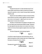
The simulation on the throttle body is based on the control input of the angle of the throttle plate. The rate in which the model induces air into the intake manifold can be expressed as the outcome of two functions. One is the function of the throttle plate angle and the other is an atmospheric function of the manifold pressure. In the case of greater vacuum, the flow rate through the throttle plate is sonic, therefore, it is only a function of the throttle angle.
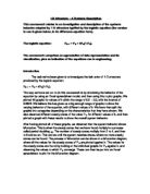
Intake manifold
Intake manifold has a different equation to the manifold pressure. The difference of the incoming and outgoing mass flow rate provide a net rate change of mass with respect to time. This according to the ideal gas laws is proportionate to the time derivative of the manifold pressure.
Note, Crossley and Cook (1991) did not use the following equation:
Intake mass flow rate
The mass flow rate of air that is pumped into the cylinders from the manifold is elaborated in the equation 1.3. This equation is derived from the mass flow rate of the manifold pressure and the engine speed.
Compression stroke
The four-stroke engine, 180° of the crankshaft separated the ignition of each cylinder. This gives a firing pattern on each alternating revolution. In the model, the intake compression, combustion and exhaust stroke happen simultaneously. To account for compression and combustion each intake charge is delayed by 180° of crank rotation.
Torque generation & acceleration
The finial part of the simulation displays the torque produced by the engine.
Modelling the open loop simulation
Figure 1.1 demonstrates what that top level of the Simulink hierarchical structure that can create. This model takes the advantage of Simulink’s hierarchical modelling capability. The blocks below are made up of smaller blocks.
Figure 1.1 the top level of Simulink engine
The models for the throttle and intake manifold subsystem are depicted in figure 1.2. The throttle valves behave in a non-linear way; this is modelled in a subsystem with three inputs. Simulink uses the equation from in the block for the throttle given in equation 1.1. A switch block determines if the flow is sonic by the comparison of the pressure ratio to the switching over threshold, which is set at one half of the equation, see 1.1.
In the sonic regime, the flow rate is only a function of the throttle plate angle. The sign Block determines the flow from high to low pressure.
The min block ensures that the pressure ratio is kept at unity or less.
The intake manifold uses a different equation as in (equation 1.2) to calculate the manifold pressure. Simulink has a function block that also calculates the mass flow rate into the cylinder, the function of the manifold pressure and engine speed (equation 1.3).
Manifold dynamics
Intake & compression
The four stroke cycle for one cylinder. In the intake stroke the intake block integrates the mass flow rate from the manifold.
Combustion
Engine torque is a function of four variables. The Simulink model implements Mux block to integrate these variables into a vector that produces input to the torque Gen block. The function block calculates the engine torque, as indicated in (equation 1.4). The torque, which loads the engine, is calculated by the step functions in the drag torque block. This is subtracted in the dynamics subsystem. The difference divided by the inertia provides the acceleration.
Results at idle.
The simulation has become unstable because the controller is out of the loop, in reality the engine would stall.
Fugure1.3 the engine speed
Modelling the closed loop simulation
The enhanced model shows the flexibility and capabilities of Simulink. The objective of the controller is to maintain the engine speed with a fast throttle actuator causing changes in the load or torque to have minimal effect. This is accomplished in simulink by the addition of a discrete-time PI controller to the model shown in figure 1.4.
This represents the same model described earlier, but with a closed-loop system.
A control law was selected, which uses proportional plus integral (PI) control. The integrator is required to adjust the steady-state throttle as the operating point change. The proportional term compensates for the phase lag caused by the integrator.
Figure 1.5: speed controller subsystem
A discrete-time controller, capable of microprocessor application is employed. The integral term in equation 1.6 must be realised with discrete-time approximation.
As in industry, the controller synchronized with the crankshaft. The controller is embedded in a triggered subsystem that uses the valve timing signal. The detailed construction of the controller subsystem as shown in figure 1.5; controls the engine speed when load is applied.
Results
Controller input Pi = 30
Proportional gain = 0.0614 integral gain = 0.0723
Controller Output T_A = 8.973
Figure 1.6:
Engine speed form 1000 Rpm to2000Rpm and 1000Rpm to 3000 Rpm
Load (Nm)
step = step time 2 initial value 25 finial 20
step 1 = step time 8 initial value 0 finial value 5
Conclusion
The Simulink able to accuracy model an S.I engine with a high level of accuracy. Simulink has shown that the engine needs a controller to maintain engine stability.
References
- P.R. Crossley and J.A. Cook, IEE International Conference “control 91”, Conference Publication 332 vol. 2, pp.921-925, 25-28 March 1991, Edinburgh, U.K.
- Dr M Ebrahimi lecture notes on simulink model layouts.