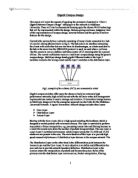
- Core Layer
- Distribution Layer
- Access Layer
Starting with the Core Layer, this is a high speed switching the backbone which is designed to switch packets with minimum latency. This layer is restricted to perform any packet or frame manipulation, e.g. processing access lists and filtering because as a result this would slow down the number of packets being switched. The core layer is a pure Layer 3 switched environment, which simply means that VLANS and VLAN trunks are not present in the core. The main function of this layer is to provide high speed connectivity between all distribution layer devices in the campus network. The
The Distribution Layer on the other hand is the differentiation point between the Access Layer and the Core Layer. It main objective is to define and differentiate the core and also to provide network boundary definition. Distribution Layer is the location where the manipulation of packets and frames take place. Some of the primary roles the distribution layer carries out are; Packet manipulation, filtering, route summarization, route filtering, route redistribution, inter VLAN routing and security
Access Layer, at this stage the local end users have been granted access to the network. This layer also has the capability to use ‘access lists’ or ‘filters’ to optimize and synchronise with a particular set of users “normally used when participating in video conferencing”. The access layer can include shared bandwidth, switched bandwidth, MAC layer filtering and Micro segmentation.
Multilayer designs are considered to being modular and can also have numerous scales as the foundation of their building blocks which can be incremented. The reduction of problems caused by a simple mistake with the configurations or even malfunctioning equipment could also occur within the Layer 3. Another protocol that should be included and provides redundancy and fast convergence to the wiring closet is the Hot Standby Routing Protocol ‘HSRP’. Using Multilayer modeling preserves the existing addressing of the campus network based on the specific routers and hubs it’s configured on. Layer 2 switching provides similar benefit compared to the previous layer within routing in campus network design, with the added performance of packet forwarding dealt with by a specialized hardware. Positioning the layer 3 switching in the distribution layer, the backbone of the campus segments the campus into smaller, more manageable pieces. This multilayer approach combines layer 2 switching to attain a robust and highly available campus networks. Layer 2 devices should be employed and placed in the core with links to the distribution layer switches and connected via Gigabit Ethernet uplinks.
The Network Campus Deign can be broken down into several sections and can be examined using VLANs. Also known as a virtual LAN, this is a group of end station with a common set of requirements, independent of their physical location, that communicate as if they were attached to the same wire. VLANs are essentially Layer 2 constructs, and IP subnets are Layer 3 construct. VLANs allow you to group ports on a switch to limit unicast, multicast and broadcast traffic flooding. Within a campuses LAN that employs VLANs, often ‘one to one relationships’ exists between VLANs and IP subnets to allow flexibility in LAN design. VLAN is an extended layer 2 switched domains also it has the same characteristics of a failure domain, broadcast domain and of the spanning tree. VLANs can be used to segment the campus network logically, deploying pervasive virtual LANs throughout the campus adds to the complexity. Avoiding loops and restricting one VLAN to a single Layer 2 switch in one wiring closet will minimize the complexity.
The multilayer designs version of its building design and is essential for a building sized network with a capacity of serving several thousand networked devices within the building. The campus design is appropriate for a large campus consisting of many buildings because it can also be implemented using the multilayer design.
.
fig2. This diagram illustrate how a typical Building block looks like
Gigabit Ethernet trunks connect layer 2 switches in each writing closet to a redundant pair of layer 3 switches in a distribution layer. The modular concept (redundant building block) can also be applied to server farms and WAN connectivity. Redundancy and fast failure recovery is achieved with HSRP configured on the two layer 3 switches in the distribution layer. Adding redundancy can be somewhere of 15 to 25 percent of the overall hardware budget. The cost is limited because only the switches in the distribution layer and backbone are fully redundant. One would assume that the cost is a rational investment because the particular building block contains critical servers and a large number of networked devices.
With the multilayer campus design consisting of a number of building blocks connected across a campus backbone, the distribution of the layers are highly essential. The layer 2 switching is used in the access layer, layer 3 switching in the distribution layer and again the layer 3 is used within the switching in the core layer. Scalability is referred to as one of the advantages of multilayer campus design as it can cover a wide scale. New buildings and server farms can be included without configuring the entire design. Multilayer campus designs take maximum advantage of many layer 3 services including segmentation, load balancing and the failure recovery. The IP multicast traffic is managed by the protocol independent multicast ‘PIM’ routing in all layer 3 switches along the traffic. Access list are applied at the distribution layer for a more strict policy control. Below I have inserted a simple diagram showing how the data flows within a gigabit multilayer campus for reference at any time.
Reference
http://www.fateback.com/data-center/tampa-florida/network-infrastructure.html