Therefore:
The reason the mass flow rate is not constant throughout the engine is because to accelerate the mass of air fuel is added and then ignited. The added fuel contributes to the mass flow rate.
The above equation is called the thrust equation and it remains true as long as the maximum Mach number < 1 in the engine and pressuree = pressure0. Fluid pressure is related to the momentum of the gas molecules and acts perpendicular to any surface. If the net pressure changes then there is a change in momentum also. This change in momentum affects the thrust:
This is a more general thrust equation but usually this addition to the equation is not used because the nozzle is designed to return the fluid back to its free stream pressure. In that case the pressure change x area term can be ignored.
Often, is calculated by where ρ = density, v = velocity and A = area.
This can be checked by looking at the units:
This is more useful from an aerodynamicist’s point of view, for instance, for a constant density flow, if we can determine the velocity through a known area we can then use the equation to find the velocity passing through any other area.
The functions of the different turbojet engine parts
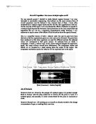
First of all, notice the aerodynamic shape of the engine as a whole. Most parts of modern aircraft are designed to produce minimum drag and maximum lift.
Intake
As the plane is flying, the first part of the engine that the air (free stream) will hit is the intake. The intake itself does no thermodynamic work on the flow but its task is to guide the air into the compressor section. The shape of the intake depends on whether the engine is designed for subsonic (below the speed of sound) or supersonic (above the speed of sound) flight. For subsonic flight, the lip (most upstream portion) is usually thick and splits the air above and below itself. In supersonic aircraft, the lip is sharp to reduce performance loss from the shockwaves experienced in supersonic flight. Also, the intake in supersonic aircraft is designed to slow the air to subsonic speeds before it reaches the compressor.
The total temperature of the intake is constant but the pressure is not. The efficiency of the intake is often characterised by the intake’s total pressure recovery. This is a ratio which can be calculated by taking the total pressure at the end of the intake/start of the compressor and divide it by the total pressure of the free stream.
For velocities below the speed of sound (M < 1)
M = Mach number ηi = intake efficiency pt = total pressure
Unfortunately, the intake creates spillage drag (Dspill). Every intake is designed to take in only the maximum amount of air the engine can cope with to reduce spillage drag but changing altitude and throttle settings cause the engine to cope with less air and the excess air is “spilled”.
Spillage Drag Equation:
V = velocity A1 = intake capture area p = static pressure K = correction factor
The correction is there because, as the air enters the intake, it accelerates over the lip and the pressure decreases (Bernoulli’s theorem) and partially cancels out the spillage drag. K is determined through experimentation as it changes for different intakes. It is noticeable that the phrase in the square brackets is very similar to the thrust equation.
Another problem with intakes is that, from the time the air enters the intake from free stream to reaching the compressor, the airflow may become distorted. The flow may be swirling, or a portion of the flow may have a higher velocity or pressure than another portion. This is all caused by the shape of the intake, the air entering the intake, and the angle of the airflow to the intake. The shape of the intake can also cause the boundary layer to become thicker in some areas. Any of these distortions can cause a compressor stall, this is when the compressor blades strike the distorted airflow and the changing air conditions cause flow separation.
The ideal intake will have a high pressure recovery, minimal spillage drag and low airflow distortion.
Compressor
All turbojet engines have a compressor. Its job is to increase the pressure of the air before it reaches the burner. Compressors use blades to increase the pressure. Each blade acts like a small aerofoil, adding a small amount of pressure. There are two main types of compressor: axial compressor and centrifugal compressor.
Figure 1: axial compressor
Figure 2: centrifugal compressor
A multi-stage axial compressor works by having several rows of aerofoils containing two different types of blades: rotors and stators. The rotors are attached to the shaft and rotate whilst in between each row of rotors is a row of stators which remain stationary to, along with increasing the pressure, keep the flow parallel to the axis and not travel around the shaft with the rotors. The pressure increase (compressor pressure ratio = CPR) is measured as the ratio of the air total pressure exiting the compressor to the air pressure entering the compressor.
Burner
The burner sits between the compressor and the turbine. It injects fuel into the high-pressure air, ignites it and it burns. The result is a high temperature exhaust gas which turns the turbine and produces the thrust through the nozzle.
The burner is in the shape of an annulus, similar to a doughnut. The material that a burner is made from needs to be very heat resistant because of the extremely high temperatures involved. There are several main designs but all consist of an outer casing to protect the surrounding parts of the aircraft from the heat and an inner liner which is perforated to improve the mixing of the fuel and air (see fig. 3).
Figure 3: burner "cans" which are situated around the shaft
The burner pressure ratio (BPR) remains nearly the same over the burner section.
Turbine
The turbine takes some of the energy from the hot, high-pressure air so that it can power the compressor. This saves a lot of money and fuel as the only other option is to power the compressor separately. Since the fluid loses energy across the turbine the pressure drops. Because the pressure is very high entering the turbine, the pressure gradient dictates that there is a bigger decrease in pressure in comparison to the increase in pressure in the compressor. This is why one turbine stage can generate enough power for a multi-stage compressor. The blades in a turbine are often banded together because the high-pressure air can leak out, reducing the efficiency of the turbine. Also, the extremely high temperatures concerned require the material to be very heat resistant and there is often a cooling system involved. This system usually takes some of the cool air from the compressor and passes it through the hollow turbine blades which have many small holes in the surface to cool the exterior. The pressure decrease over the turbine (turbine pressure ratio = TPR) is measured as the ratio of the air total pressure exiting the turbine to the air pressure entering the turbine.
Nozzle
The nozzle is the last section and it is from this that the thrust is finally produced. In addition, the design of the nozzle fixes the value of the maximum mass flow rate through the method of choking. The minimum cross-sectional area in the nozzle, the throat, limits the mass flow rate. Nozzles come in a variety of shapes and sizes depending on the mission of the aircraft.
Figure 5: convergent nozzle Figure 6: convergent-divergent (CD) nozzle
The above diagrams show the basic designs for nozzles. The maximum airflow speed through the throat is Mach 1. The convergent design is used in most simple turbojets such as commercial jets because there is no need for a large airflow range. Alternatively, the CD design is used in more sophisticated high-speed aircraft that use afterburners because the exit airflow is much higher than the free stream air that it enters and large drag penalties are incurred. With a larger exit area after the throat, the exit flow velocity drops, reducing drag. The divergent section increases the weight which will require more thrust and fuel to get it off the ground and variable geometry CD nozzles used in fighter planes increase the weight even more. Whereas a commercial aircraft will travel essentially forwards and rely heavily on cost efficiency, a military aircraft must be extremely manoeuvrable, extremely fast and must have powerful acceleration.
Afterburner
Afterburners can usually be found in fighter planes. Travelling through the speed of sound involves a lot of drag. This drag needs to be compensated by plenty of thrust which is provided by the afterburner. After the burner, energy is taken out of the flow by the turbine but energy is put back in by the afterburner. This is done by injecting fuel directly into the hot flow after the turbine. However, the combustion is not as efficient as in the burner section and a lot of fuel is used up providing the extra thrust.
Unfortunately, the increased temperature requires a larger exit area in the nozzle to pass the same mass flow rate. To achieve this, the variable geometry CD nozzle increases the exit area
Bibliography
Internet sites
Books
Mechanics of Flight by A.C.Kermode 1996