- An Office Block
- An Executive Block
- A Supply Department
The mainframe in the Main Site is used for storing the database for the stock control; the main frame is used in a stand-alone fashion, and is not connected in a network setting.
The Office Block consists of 4 departments with a total number of 50 employees divided in the following manner:
- Accounts Department (12 employees)
- Typing Centre (13 employees)
- Pay Department (11 employees)
- Credit Control (14 employees)
The Office Block does not have any computers and is not connected to the mainframe computer; all the administration duties are carried manually.
The Executive Block consists of 11 offices, and each office has 3 computers used in a stand-alone fashion, there are also 11 secretary terminals, one in each office, which are connected with the mainframe computer.
The Supply Department holds all the stock and is made up of 2 departments:
- The Stock Buildings
- The Workshops
The Stock Buildings have no computers and are split into 4 departments:
- Plumbing
- Wood
- Electrical
- Building Material
There are also 4 different Workshops that have no computers and they are split in 4 departments:
- Double Glazing
- Kitchen Units
- Furniture
- Bathroom Units
The Supply Department has also 20 PCs that handle all the stock control duties; the PCs have no network connection with the Stock Buildings or the workshops, so they access the information manually from the stock buildings.
4.2 The Subsidiary Firms:
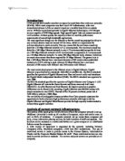
The following diagram shows the layout of the Subsidiary Firms:
Fig. CURRENT DESIGN OF THE SUBSIDIARY FIRMS
There are 10 subsidiary firms that treat the Main Site as the headquarters. Each subsidiary firm has at the moment 2 remote point of sales terminals (POS). The POS terminals are used in a stand-alone fashion and have no network connection with the Main Site.
4.3 The Design Office:
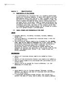
The Design Office is composed of 6 teams of designers with their own offices; each team has 6 designers with their own PCs. The designers use advance CAD packages to design and develop products for kitchens, glazing and building extensions.
The design office does not have any network connections with the main site.
The following diagram shows the existing layout of the design office:
Fig. Current layout of the Design Office
5. REQUIREMENTS:
5.1 Main Site:
A.A. Builder is not considering disposing of the mainframe computer for the new proposed network
Design, and wants it to be integrated in the network system.
Currently there are a number of 11 offices in the Executive Block, each office has 3 stand-alone computers, and each office has one secretary with one PC connected to the mainframe, bringing the total number of PCs in that department to 44 PCs. Nevertheless more computers might be implemented in the future network design.
The office block is made up of 50 employees spread among 4 different departments with no computers, therefore the assumption is that they conduct their administrative duties manually, this block requires computers in order be part of the computerized network system.
The supply department is used for holding all the available stock, it consists of 4 separate stock buildings (plumbing, wood, electrical and building material), and it also possesses 4 different workshops (double glazing, kitchen units, furniture and bathrooms), all of which have no computers, and need to have computers installed in order to integrate into the new network system.
There are also 20 PCs in the supply department used for stock control which gather information manually from the stock buildings, therefore a computerized network link will have to be established between these PCs and the stock buildings.
5.2 The Subsidiary Firms:
The 20 POS terminals used by the subsidiary firms are currently operating in a stand alone fashion and need to be integrated in the new network system in order for them to have access to the database for all their daily transactions. The number of POS terminals can be increased if the need ever arises.
The subsidiary firms have no network communication link with the main site and will have to establish one in order to access the accountancy facilities and the database for prices and stock control.
5.3 The Design Office:
The design office consists of 36 designers, each with their own PCs, operating in a stand alone fashion with no network communicate link with the main site, therefore the computers will have to be updated and connected in a network environment with the main site.
5.4 Security Cameras:
A.A. Builder plans to acquire additional security cameras for surveillance purposes of the main site and would like some recommendation on setting up their security camera systems.
6. PROPOSED LAN DESIGN:
6.1 Network Topology:
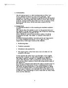
The proposed architecture to be used on the whole of the A. A. Builder network is the Switched Ethernet LAN architecture. It is based on a star topology which is designed with each node (file server, workstations, and peripherals) connected directly to a central network hub or switch.
Data on a star network passes through the hub or switch before continuing to its destination. The hub or switch manages and controls all functions of the network. A star topology is easy to install and wire, it is also easy to expand or reduce by adding or taking off hosts, this is very compatible with the A. A. Builder company’s requirements if they ever decide to add more POS terminals in the subsidiary firms or any other part of the network.
Unlike other topologies, where if a host fails, the whole network fails, the star topology makes it easier to detect faults in a network, and isolate any faulty parts if necessary.
Fig. Star Topology
Switched Ethernet is based upon the star topology and uses only switches instead of hubs. The switch is designed to manage a set of separate point-to-point circuits. That means that each circuit connected to a switch is not shared with any other devices; only the switch and the attached computer use it, this means that collisions are less likely to occur within a star topology, as a switch separates collision domains by separating hosts into a number of collision domains. The switch uses a forwarding table that lists the Ethernet addresses of the computers connected to each port on the switch. When a switch receives a packet, it compares the destination address on the packed to the addresses in its forwarding table to find the port number on which it needs to transmit the packet.
Fig. Switched Ethernet
6.2 Backbone Architecture:
The core network for the A. A. Builder will be a Chassis-Based collapsed backbone with redundancy, which is formed with a mixture of layer 2 and layer 3 switches.
The reasons for choosing that specific network backbone as supposed to other network backbones could be resumed in the following points:
- Collapsed backbones use a star topology with one device, usually a switch at its centre, which matches the network topology chosen for the whole network.
- Collapsed backbones use more cables but in the other hand they use fewer networking devices in the network, this reduces costs and greatly simplifies network management.
- Performance is greatly improved. With other backbones (routed or bridged), the backbone circuit is shared among many LANs, each has to take turns sending messages. With the collapsed backbone, each connection into the switch is a separate point-to-point circuit; the switch enables simultaneous access, so that several LANs can send messages to other LANs at the same time. Throughput is increased significantly, often by 200 to 600 percent, depending on the number of attached LANs and the traffic pattern.
- All the network devices for one part of the building will be physically placed in the same room, which makes easy the job of maintenance and upgrade, although it will require more cabling. It also becomes simpler to move computers from one LAN to another, since if one switch becomes overloaded, it is straightforward to unplug the cables from several high-demand computers from the over-loaded switch and plug them into one or more less busy switches, this will in turn spread the traffic around the network more efficiently and means that network capacity is no longer tied to the physical location of the computers.
- Using the chassis switches, it is possible to plug new modules directly into the switch, with each module being a certain type of network device. The key advantage in using chassis switches is their flexibility which will allow adding new network devices with additional ports as the LAN grows and to upgrade the switch to use new technologies.