Pseudocode
The next step was to design the code using Pseudocode. Pseudocode provides a means of expressing algorithms without worrying about syntax of a particular language. I have broken it down in three steps, with stage 1 being the most ‘easiest’ form, and stage 3 being the most comparative to the final piece of code. The program is built up during the different stages and provides us with template to use when writing the code.
PSEUDOCODE - Stage 1
Set up the stepper motor pins
Set up the serial port
Get input through the computer RxD pins
Set up the various movements
Turn left
Turn right
Move forwards
Compare the character from the computer to the controls and execute that command
PSEUDOCODE - Stage 2
Set up the stepper motor pins
Pins P1.0 to P1.3 for motor 1
Pins P1.4 to P1.7 for motor 2
Set up the serial port
Set the receive pin of the port
Wait for a command from the Wap interface
Begin
if command = 1
move left
Else if command = 2
move forward
Else if command = 3
move right
End
PSEUDOCODE - Stage 3
Set up the stepper motor pins
Pins P1.0 to P1.3 for motor 1
Pins P1.4 to P1.7 for motor 2
Set up the serial port
Set the receive enable bit (REN) in SCON
Set up various movements (subroutines)
Forward
8 steps to move both motors forward
Left
8 steps to move the left motor forward (Right turn)
Right
8 steps to move the right motor forward (Left turn)
Get Command from serial port and store in ACC
Character from serial port compared to various registers
A = 1
B = 2
C = 3
Compare and jump if not equal
If ACC = A then go to subroutine Left
Else go to Skip1
Compare and jump if not equal
Skip1 If ACC = B then go to subroutine Forward
Else go to Skip2
Compare and jump if not equal
Skip2 If ACC = C then go to subroutine Right
End
Now the final stage of my pseudocode was done I could start designing the code. I will explain different parts of the program and how it works on the next few pages.
The Code
Setting up the Serial Port
My first aim was to set up the receive pins on the serial port. The serial buffer registers SBUF and serial control register SCON, allow access to the serial port. To initialise and access the serial port, the receiver enable bit (REN) in SCON must be set by software to enable the reception of characters. I am setting this up at the start of a program, in two ways.
SETB REN
This sets REN, but I used the instruction,
MOV SCON, # xxx1xxxxB
this sets and clears the other bits in SCON.
Stepper Control
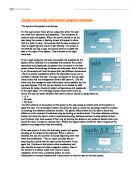
A stepper motor has a permanent magnet rotor and a stator consisting of two coils. The rotor aligns with the stator coil that is energised. By changing which coil is energised, the rotor is turned. I will explain with the help of diagrams how this works.
Step 1
Step 2
Step 3
Step 4
Now I explained how the stepper motor works, I had to design the stepping sequences in order to make the motor move. I used unipolar mode of operation as only four switching transistors are used.
I am going to use Half-Step sequence for clockwise rotation, which has 9 steps. It starts from step 1 to step 8, then back to 1 again.
LEFT:
MOV P1,#ST1 ;FIRST STEP
LCALL DELAY
MOV P1,#ST2 ;SECOND STEP
LCALL DELAY
MOV P1,#ST3 ;THIRD STEP
LCALL DELAY
MOV P1,#ST4 ;FOURTH STEP
LCALL DELAY
MOV P1,#ST5 ;FIFTH STEP
LCALL DELAY
MOV P1,#ST6 ;SIXTH STEP
LCALL DELAY
MOV P1,#ST7 ;SEVENTH STEP
LCALL DELAY
MOV P1,#ST8 ;EIGHTH STEP
LCALL DELAY
MOV P1,#ST1 ;FIRST STEP
LCALL DELAY
RET
#ST1 – #ST8 are the steps in which the rotor moves, when the steps have been completed one full cycle is executed. The delay, which I have set up;
DELAY:
MOV R1,#80H
LOOP1:
MOV R0,#0
LOOP2:
DJNZ R0,LOOP2
DJNZ R1,LOOP1
RET
Controls the speed of the stepper motor, if I was to load different values into the register other than 80h, I would get various speeds.
Input
The serial port is now set, and I am ready to receive data from the pins. This subroutine waits for the receive interrupt flag (RI) to be set, indicating a character is waiting in SBUF to be read. When RI is set, the JNB instruction falls through to the next instruction. RI is cleared and the code in SBUF is read into the accumulator. The P bit in the PSW establishes even parity with the accumulator. CY = 0 if there is no error, and a 1 if there is an error. Finally, ACC.7 is cleared to ensure that only a 7-bit code is returned to the calling program.
ORG 8100H
INCHAR: JNB RI, INCHAR
CLR RI
MOV ACC, SBUF
MOV C, P ; If C=1 – odd parity. C=0, even parity
CLR ACC.7
SJMP SKIP
RET
I have also put a short jump instruction, above RET. When the data is in the accumulator, the routine makes a short jump to label SKIP SJMP SKIP. Which I have described next.
Controls
The robot must be able to move left or right or go forward. In order to define which movement I want, I have to set up a routine that will compare the instruction received from the serial port to a routine, which I defined earlier. For example, if going forward was equalled to an ASCII character 1, then I would compare the instruction, which is received from the serial port, and compare to one of the three commands I made earlier. Here is the code.
MOV R4,#01H ;CHECK THIS BIT AT UNI?
MOV R5,#02H
MOV R6,#03H
SKIP CJNE ACC, R4, SKIP1 ; C ACC & R6 AND J TO SKIP1 NE
LCALL LEFT ; GO TO SUBROUTINE LEFT
SKIP1 CJNE ACC, R5, SKIP2 ; C ACC & R6 AND J TO SKIP2 NE
LCALL FORWARD ; GO TO SUBROUTINE RIGHT
SKIP2 CJNE ACC, R6, ; C ACC & R6 AND J TO SKIP3 NE
LCALL RIGHT ; GO TO SUBROUTINE FORWARD
RET
Lets say R4 is equal to 1, and the data received from the serial port is stored in the accumulator. CJNE, compares the ACC, and R4 together, if they aren’t equal then it jumps to the next label, which is SKIP1, and if it is equal it jumps to the routine LEFT. This is the same procedure for the other two, but with left and right.
Final Code
You can view the code in the appendices, where you will find a robot.asm and robot.lst.
Evaluation
The code worked fine, but there could be significant improvements made to this,
Such as:
- Structuring the program, by using registers to store the current index (0 to 7). Writing a subroutine called STEP, can update the current index, and drive the motor.
- I could modify the delay sequence, so the count loaded into r1 is changed smoothly as the motor accelerates and decelerates.
- Implement four full stepping sequences instead of half stepping.
- and, instead of the foreground program timing the stepping sequence, I could use a timer to issue interrupts upon overflow
These changes would make the program a lot harder to produce, but would give greater control over the robot. If I had enough time, and practice, I would implement these changes into the program.
Testing
Bibliography
-
Yeralan, Sencer and Ahluwalia, Ashutosh. ‘Programming and Interfacing the 8051 Microcontroller’, 2nd Edition (1996), Addison Wesley.
-
Mackenzie, Scott, ‘The 8051 Microcontroller’, 3rd Edition(1999), Prentice Hall
-
Predko, Myke. ’Programming and customising the 8051 microcontroller’. 2nd Edition (1998), The Electronics Authority
- CCM2081Microprocessing and C++ Reader, Gerry Woof, Semester 1 2001/2002
-
Heathcote, PM, ‘A Level Computing’ 3rd Edition (1998), Letts