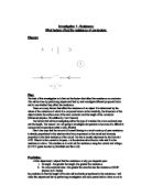
We can see that since, the electrons are repelled at the negative end, they go towards the positive end, and so uniformly travel from negative to positive. For e.g. if we open the window of a very cold classroom, the heat sweeps inside, to nullify the effect, due to the potential difference in the temperatures. Also if we place water at a higher altitude, the pressure is more; so the water moves down to nullify the effect, due to potential difference in pressure. Thus we see if a potential difference is created in a wire, the electrons, move, in order to nullify its effect.
How do we create a potential difference?
By using a battery or generator, we can create a potential difference, which causes the electrons to move, thus conducting electricity. When we connect the wire to the positive and negative ends of a wire, we can see that there is a potential difference on the two sides, i.e. one is positively charged, and the other is negatively charged. Thus the electrons move from the negative end, to the positive end, in order that the effect of the introduced potential divider is nullified.
Circuit
Flow Of electrons
+ -
Battery
RESISTANCE
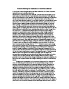
However, the electrons do not just move easily, as though it was a 100m straight race. Instead, it is more like a 100m hurdles race, where they collide with the vibrating atoms. This is resistance. Resistance in general in electrons, is the obstruction, or collisions faced by the electron. In order to find out how, much resistance, there is, we use ohm’s law. Ohm's law states that the amount of current flowing in a circuit made up of pure resistances is directly proportional to the electromotive force impressed on the circuit and inversely proportional to the total resistance of the circuit. The law is usually expressed by the formula I =V/R, where I is the current in amperes, V is the electromotive force in volts, and R is the resistance in ohms. This enables us to work out the resistance using the current and Voltage.
Bur we can also measure resistance in a circuit using a voltmeter and ammeter. This is done by: V/I= Resistance.
Copper wire
V Gradient = V
I
I 1 = V_
Gradient I
But this resistance can be varied, and; it is the factors that affect, and cause the resistance to vary, that I will be tackling in this coursework. In order to explain anything, to another person, we use examples, or models. In the same way, I will make use of two to three examples, or models, to help prove my experiments.
One such model is the water model.
Here, the water acts as the electrons, the pump as the battery, and the pipe, as the wire. If water tub is stored at a higher altitude, the water pressure increases, and so the water flow faster. As diameter of the pipe increases, the amount of water flowing through increases. Thus I predict, that the width of a pipe affects the resistance of a wire. When the length of the pipe is increase, the water takes more time to pass through, and so takes more time. Thus I predict that length affects the resistance of a wire. Also, when the power of the pump increases, the water travels quicker, so I predict that potential difference, affects resistance.
Another model is my own invention, which I call the “ Dance floor Tech” model.
There are many factors, that affect the resistance of a conductor, and it is these factors, that I will be examining in the coursework. They are:
- THICKNESS
- LENGTH
- MATERIAL
- TEMPERATURE
In order to experiment and to see if these factors actually affect the resistance, we test using two to three variables of each factor, BUT at the same time, keeping the other factors the same.
Thickness.
When we increase the thickness, there is more electron space, as the width increases, so the electrons have fewer collisions. We are able to see this, also in my model, where if we increase the dance floor space, the people dancing are spread even more evenly, and far apart, and so the man has fewer collisions. Also in the circuit, following this explanation. It is possible to see, that if we increase the width, then there is more space for the electron to pass through, with fewer collisions. Thus I presume that when you increase thickness, resistance decreases.
LENGTH.
When we increase the length, the possibility of a collision, increases, which is also viewable in my model, where if we increase the length of the dance floor, the chance that the man will collide increases, as he has a longer way to walk. In the circuit, we can see that if the wire length is longer, then the possibility of more collisions increases. Thus I presume that when you increase the length, resistance increases.
MATERIAL.
Different materials have different no of free electrons, which in the model is different no of men, going to the bar. In the circuit, also, different metals, have different number of atoms, so in copper, there are less number of atoms, compared to steel, thus it conducts electricity, better with less resistance, as there are less collisions. As we can see in the circuit, if we different metals have different number of atoms. Thus I presume, that the more the no of free electrons, the more the current and the less the resistance.
TEMPERATURE
When you increase the temperature, you increase the vibrations of the atom, so there is more chance of the electron, colliding with the atom. In my model, if you increase the frenzy with which the crowd dances, you increase the chance of them hitting the man. As it is visible in my circuit, difference in temperatures, causes the atoms to vibrate with greater vigor, and so there is more chances of the electron colliding with it. Thus I presume, that when you in crease the temperature, you increase resistance.
In addition, by using a rheostat, or in other words, a variable resistor, we can cause changes in the current. Thus when the index of the rheostat is moved left, the voltage and current decreases, and the opposite happens, when it is moved right. Thus it is possible to state that voltage and current are proportional.
In my experiment, I will use a varying current, in order to find if the resistance is a constant, and if my predictions are predicted right. If I use a high range of voltage values, then the electrons move with a greater force, and so the collisions will be more impactful, and so, more energy will be lost in these collisions, and so, the wire will heat up more. As a result, the resistance value will be higher, as resistance increases, with temperature. Nevertheless, if my voltage value is too low, then the readings will be so low, that it will not be able to be picked up by the ammeter. In addition, the voltage to be selected differs, from conductor to conductor. For example, if I choose copper as my conductor wire to be tested, then I will have to choose a lower range of voltage values, in order that the rapid heating of the wire is prevented, which could result in the wire snapping. But if the metal to be chosen has a lower conducting power, then it is possible to choose a little higher range of voltage values. I have chosen to use NICHROME, as it is very suitable, since it has moderate resistance. At the same time, I will choose a current within the range of 0.0 - 2.0, as it shows a reasonable change in the current value, without causing much heating.
EXPERIMENTAL PROCEDURES
In order to record my observations, I will use the following types of observation tables, and I will display the manner in which my wire will be setup, in order that I will be able to experiment with them.
- LENGTH
For length, we have to make sure that only the length is changed, and that all the other factors are kept as a constant, i.e. the thickness, the material, and the temperature.
Thickness = 0.3 mm
Material = nichrome
Temperature = room temperature
The index is adjusted, to vary the resistance, 10 alternative readings of current and voltage are taken, at uniform intervals. For every 0.2 volts, I will be measuring the current, for each wire, and I will be observing, and recording the readings on the ammeter, in a table like this.
My expected graphs will look like this.
The shorter the wire, the lesser the resistance there will be.
Ω = 1/ gradient
∴ 20 cm wire has the greatest gradient, so less resistance. The resistance on should tally with my table readings; otherwise, it will mean that there is an error somewhere.
-
Thickness
For thickness, we have to make sure that only the thickness is changed, and that all the other factors are kept as a constant, i.e. the length, the material, and the temperature.
Length = 50 cm
Material = nichrome
Temperature = room temperature
My expected graphs will look like this.
The thicker the wire, the lesser the resistance there will be.
Ω = 1/ gradient
∴ 3 mm wire has the greatest gradient, so it has the least resistance.
- Material
For material, we have to make sure that only the material is changed, and that all the other factors are kept as a constant, i.e. the length, the material, and the temperature.
Length = 50 cm
Thickness = 0.4 mm
Temperature = room temperature
My expected graphs will look like this.
Different conductors have different resistances, thus, the copper wire has the greatest gradient, and so it has the least resistance.
In order to increase the reliability of my resulting readings, I am going to record the readings while increasing and decreasing the voltage supplied.
I will also make use of series and parallel circuits, to verify the law of resistance.
To investigate the law of resistance for length. I will use the following type of board for this.
The resistance for the 25 cm wire is shown by :
The resistance for the 50 cm wire is shown by :
This the type of graph I would be expecting to get. As you can see, the line for the 20+30 cm graph falls just a little short of the 50 cm.
R = R1+ R2
In addition, to verify the law of resistivity for thickness, we use parallel circuit, which are connected in this manner:
Here we will test to see if the resistance of two .4 mm wires connected in a parallel, is equal to the resistance of a .56 mm wire. This should get me a graph like the one that follows:
In order to plot this type of graph, I will have to record my results in a table like this:
The resistance for the 0.4 mm + 0.4 mm wire is shown by :
The resistance for the 0.56 mm wire is shown by :
I did a prior test, or an introductory pre – experiment test, to get me used to how to know to work the rheostat, and connect the circuit, and the results I got, are on the next page.
Analyzing evidence
As you can see from my graphs, which are more or less like the graphs, I had expected to get, in my planning,
In order to show that when the length of the wire was changed, the resistance changed proportionately, I created this bar graph.
Thus as you can see, when the lengths in crease, the resistance of the wire increases, as there are more collisions between the electron, (which is moving from the negative end to the positive), and between the atom. When length is doubled, resistance doubles. Therefore length is directly proportional to resistance.
In addition, I compared the resistance obtained from the tables, when I changed the thickness of the wire, and this is the resulting pie chart.
Here too, it is plain to see that when the thickness doubles, the resistance is halved. This is due to, when the thickness increases, there is more space for the electron to pass through, without colliding, and thus resistance decreases. Thus resistance is inversely proportional to resistance.
Where as in my series and parallel graphs, the gradient achieved for both the graphs is almost the same, thus I state that the resistance of a longer wire, is the same as two shorter wires connected together in a series circuit. In addition, the resistance of a thicker wire is the same as that of two thinner wires connected in a parallel.