of a wire is directly proportional to the resistivity. Therefore a wire with a high resistivity, like constantan, for example will have a high resistance. But, a wire with a low resistivity, like copper, for example has a low resistance.
Current in a wire is determined by:
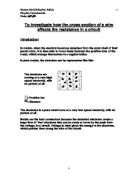
- How many electrons are in the circuit. The more electrons the greater the current
- How fast the electrons are moving at. The faster the speed, the greater the current.
To find out the resistance in a current you have to use the formula:
Voltage
Resistance =
Current
R (Ω) = V
I
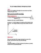
From previous research, it has been discovered that a voltage/current graph for a wire, is a straight line through the origin. This means that the voltage across the wire is proportional to the current through it. Therefore if the voltage would double, the current will double.
George Simon Ohm (1789-1854) was the German physicist who in 1827 discovered the law that the current flows through a conductor proportional to the voltage and inversely proportional to the resistance. Ohm at that time was a professor of mathematics in Cologne. His work was coldly received. The Prussian minister of education announced that "a professor who said such craziness was unworthy to teach science." Ohm resigned his post, went into academic exile for several years, and then left Prussia and became a professor in Bavaria.
Ohm’s law basically reflects these points:
When a current flows through the wire, the graph of voltage/current is a straight line through the origin.
This will tell us two things:
- The voltage is proportional to the current
- The resistance is constant.
Ohm’s law will apply as long as the physical conditions of the wire (e.g. its length, cross section, and temperature) remain the same.
Because of Ohm’s law, the amount of current provided shouldn’t matter because the resistance will be the same. However, from previous experiments, if too much current is supplied the wire will heat up, and it will increase the resistance. The current should not be more than 1A because it will make the wire heat up, but it shouldn’t be too small either because then it will be hard to measure the current accurately.
Experiment 1
Aim- To investigate how the cross section of the wire affects its resistance
Apparatus- Power Supply- Power source for circuit
Wires- To connect the whole circuit together
Ammeter- To measure the current
Voltmeter- To measure the voltage
Resistor- Wires (The resistance caused when the current goes through it)
SWG Conversion graph- To convert the SWG into inches to find out the area
Wire Cutter- To cut the wire to the right size.
We need the voltmeter and the ammeter to work out the resistance in the wire, using the formula - R = V
I
24 SWG
26 SWG
Preliminary tests
I will first test different lengths of wire to check what would be the best length of wire to use for this test, making sure it is not too long so there is a high resistance, and not too short so there is very small resistance. I will be using 40cm length of wire, because it will not give a very high resistance or a low resistance because of the length of the wire.
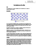
Diagram
Method
-
1st I will assemble the circuit as shown above.
- Test the wire with different amount of voltages, varying from 2V – 12V.
- I will also be varying the cross section of the wire from 24SWG – 32SWG.
- I will measure the voltage and the current using the voltmeter and the ammeter, so then I will be able to work out the resistance using Ohm’s law.
- I will be switching the power off immediately after I get my results to prevent the wire of heating up, because then the resistance of the wire will increase, therefore making the test unfair.
I will vary the voltage so that I can prove that the voltage and resistance are proportional, therefore if I would double the voltage, the resistance will also double.
I will vary the thickness of the wire to prove that the thicker the wire is the less resistance it will cause, because then the electrons have more space to flow through, so then less collision will take place, which means the electrons will not lose a lot of energy and heat will not be produced, making the resistance level stay low. I will do this by changing the wire of the circuit to a thicker or thinner wire.
The factor that I will keep the same is the length of the wire in the circuit, by using a ruler to measure the length before using it, so that the test will be fair as the length of the wire also affect the resistance of the circuit.
I will need to work out the resistance produced from the wire to prove the theory that the more cross section there is in a wire, the less resistance will be produced.
The factor that I cannot control, but will take account is the temperature of the wire. When it is used the wire heats up, which causes the resistance to increase. I will try to control the wires temperature, by switching off the power supply as soon as I have gotten my results that I need, then wait a little bit so that the temperature will go down, so that then the test will be fair.
The safety precautions that I will take is making sure that the power supply is always off unless if I need it, so that when I change the wire for example, I will not get shocked. I will also make sure that there is no water next to the circuit, as the water may conduct the electricity elsewhere, which may cause damage. I will also be making sure that no part of the circuit is touching to another part of the circuit so no short circuit can take place.
Results
My results have been clearly shown in these tables below. These tables show the voltage produced in each experiment, the current of each experiment and the resistance there is in each experiment. I know that my results are correct, because there are no figures that have come out wrong to disprove my theory. I have also drawn some graphs to prove that the voltage produced in a circuit is directly proportional to the resistance in the circuit. This graph was not hard to draw as the graph comes out to be a straight line. In the table there are different amounts of voltages because for that cross section of the wire the current was to big too measure on the ammeter, therefore I could not work out its resistance.
Conclusion
In the table above I have compressed all the information clearly into one simple table to prove my theory. This table above proves the theory that the bigger the cross section of the wire, the less resistance is produced in the circuit. I know that my answers are reliable because there are no results that have come out wrong, disproving my theory. My graph that I have drawn will prove that my results are correct because as the cross section in proportional to the resistance it will have a strong positive correlation giving it a straight line. The reason that it will not be an exact straight line is because the temperature may have varied, and the readings might be slightly off.
Evaluation
My experiments and investigation went very well. My results were very accurate as they all went up in proportion. But, there was a few experimental errors, but no result was off by a lot, but a few were off a little bit. I know this because when I drew my graphs I saw that the point didn’t fit in the straight or curved line. These errors could have been caused by:
- The voltmeter or ammeter was flickering therefore it was hard to get the exact reading.
- The wire could have mistakenly been measured a bit too long or too short.
- The wire could have heated up during the experiment, therefore getting a higher resistance.
- The wire may have had some kinks in it.
Due to all these experimental problems, reading the voltmeter, ammeter or the measurements of the wire makes my experiment not that reliable.
As I had a few errors in my graphs I plotted another line using my graphical results to see if it would make a difference, if those results would be any better, but if you look at the graphs you can see that they are both practically the same, and the same points that are wrong in the calculated line, they are also wrong in the graphical line.
Extension
To prove my theory even further, I would repeat my experiment using:
- Different lengths of wires
- Test the wires at different temperatures
- Use a voltmeter and an ammeter which have a greater sensitivity