2) Length of wire The larger the length of the wire, the larger the resistance. This is because there are more atoms from the metal so there is more chance that the electrons would collide with one of the atoms therefore there is more resistance. This is because when you have a long wire, the electrons have to squeeze together for longer to be able to pass through the wire than they do in order to be able to pass through a short wire.
3) Type of material Different materials have different resistances because the materials' atomic structures are different so some metals have low resistances and some have high resistances. The type of material will affect the amount of free electrons that are able to flow through the wire. The number of free electrons depends on the amount of electrons in the outer shell of the atoms, so if there are more or larger atoms then there must be more electrons available. If the material has a high number of atoms there will be high number of electrons causing a lower resistance because of the increase of the number of electrons. If the particles in the material are tightly packed together, the electrons will have more collisions and therefore more resistance.
4) Diameter of Wire
As the diameter of the wire increases the resistance will decrease. This is due to the enlarged area in which electrons have to pass through, this in turn creates fewer collisions between atoms.
5) Density of Wire
When the wire has a higher density, the resistance will also be higher. This means that the wire has a larger number of atoms in a smaller space, generating smaller and more confined pathways for the electrons to flow through. This causes more collisions due to the lack of space.
6) Resistivity
Resistivity is a property that combines length, resistance and diameter of a conductor. the resistivity is used rather than the resistance because it only changes with the structure of the wire and if there’s a change in temperature.
RESISTIVITY = Resistance × Cross-Sectional area
Length of Wire
Detailed Plan
The circuit will be set up as previously shown in the ‘diagram of circuit’. The main problem that we are most likely to encounter during this is experiment, is that of the wire over-heating. This is likely to happen when the circuit is left connected for too long a period of time, whilst the results are being taken.
To avoid this problem, results must be taken quickly and adjustments made promptly. After the results are recorded, we should leave the wire and equipment to cool for a few minutes.
Explanation of Heating Effect
When the temperature of the wire increases the atoms of the metal vibrate more vigorously because of the increase in energy.
As the temperature is increased, the atoms are vibrating harder and quicker, causing the electrons more difficulty in getting through the wire as they collide with atoms in their pathway. This increases the amount of collisions therefore increases the resistance because electrons are losing energy.
Detailed drawing of Ruler
Ruler
Crocodile clip Ruler measurements
During our experiment we must make certain that each time we record a result, that the crocodile clips are exactly inline with the ruler measurements. This ensures that the results we obtain are the accurate.
Prediction
I think that as the length of the wire increases so to will the resistance, consequently decreasing the current. As the resistance of a material increases so must the force required to drive that same amount of current, therefore the rate at which the resistance of the wire increases will be directly proportional to the length.
i.e. Double the length = Double the resistance
½ the length = ½ the resistance
I think that the current will be inversely proportioned to length.
i.e. Double the resistance = ½ the current
Detailed explanation of Prediction
- +
path of electrons
A longer piece of wire will generate a larger amount of interference between electrons and atoms, as shown above. This is because, the distance that the electrons have to travel is further, as a result, creating more opportunities to collide with one another, so increasing resistance.
Final experiment
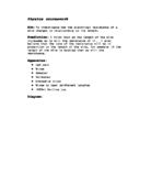
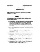
Aim: To investigate how the electrical resistance of a wire is affected in relationship to its length.
Equipment: The equipment that we will be using is as follows:
Method: Connect circuit as shown below in the diagram.
Connect the length of wire to the circuit using the crocodile clips, placed accurately on the measurements of the ruler. Activate the power and take the current and voltage readings from the meters quickly to avoid over-heating the wire. Then, repeat the experiment with the following lengths of wire connected between the two crocodile clips:
- 20cm - 30cm - 40cm - 50cm - 60cm - 70cm - 80cm
Finally, calculate the resistance, using ohms law (equation 1).
Safety precautions:
- You must ensure that the circuit is properly connected before turning on the power supply. Do not touch the apparatus until the power is switched off.
- Do not carry out the experiment in wet areas, as water is a very good conductor.
- Normal laboratory wires may melt if the power supply is too great
Conclusion
The results of our investigation show us that as the length of the wire increased so did its resistance. Our results also prove that the rate at which the resistance of the wire increased was directly proportional to the length. At 40cm the resistance was 4Ω and at 80cm the resistance was 8Ω. Therefore demonstrating that double the length = double the resistance.
As the length of the wire increased there was a larger amount of intrusion between the atoms and electrons, as shown below. This was due to the additional length of the wire, consequently increasing the number of collisions between the atoms and electrons and therefore increasing the wires resistance
- +
path of electrons
Conclusion of Resistivity Data
As a class we shared our results for five pieces of wire, each with a different diameter. We used 1 metre lengths of Nichrome wire, which is made up of 80% nickel and 20% chromium.
On a Californian database, which we found using an internet search engine, we came across ‘Ness Engineering’ which has calculated that the resistivity of Nichrome as:
ρ = 1.08 × 10 ˉ6 Ωm
Our results are not entirely accurate, as is shown by the 0.193mm² diameter wire. This is a very thin wire and so is subject to heating effects. Therefore we are unable to rely on the resistivity calculation, because as the wire is so thin its temperature will increase, in turn increasing the resistance.
Another result that is also inaccurate is that of the wire 0.914mm² in diameter. This wire is very thick and consequently, cannot be shaped easily. As a result of this, if there are any slight kinks in the wire, the length would become inexact and thus producing an imprecise result.
The rest of our results were all precise resulting as 10 × 10 ˉ7 Ωm. When compared to the calculated resistivity of Nichrome wire, we can see that our results are accurate, proving that the experiment was a success.
Evaluation
From my graph, I can see that the majority of the plots were placed exactly on the line of best fit, therefore showing that our investigation was accurate. However, I am only able to say that our investigation was accurate over the small range of wire lengths that we tested.
Possible Suggestions for inaccuracies
- The heat generated from the circuit being left connected too long may have affected the results. This would have occurred whilst results were being taken or adjustments were being made. The heat may have altered the results slightly, as the hotter the wire becomes the more the resistance increases. This would explain the results on my graph at 20 and 30cm, where the average resistances are not placed exactly on the line of best fit. This has happened because at these lengths where the wire is shorter, resistance is affected to a greater extent.
- The different lengths of wire may have been slightly affected due to each diameter. As the diameters thicken it is harder to straighten the wire exactly, so kinks may have been left in the wire whilst the experiment was being done therefore compromising the accuracy. Another point that may have been a factor for inaccuracies is if the crocodile clips were not lined up properly with the ruler measurements, as this would not have given an accurate measurement.
- As the wire we used was purchased for use in the school it was not of the highest scientific quality and so could have had an affect on our results. On the other hand the results would be relative, as none of the equipment we used was of the highest scientific quality.
Solutions to inaccuracies
- To overcome the problem of the wire over heating there are a number of measures that we could have taken in order to prevent this from happening; We could have dismantled the circuit in between taking results as if it was disconnected there would be no flowing current and so would not over heat. Whilst taking our results we could have been quicker in making adjustments and the recording of our results, as this would have decreased the chance of producing a heating effect as the circuit would not be connected long enough. One practical suggestion would be to cover the wire in a type of waterproof material and then after each recording, it would be possible to place ice over the wire in order to cool it and reduce the effects of heating.
- In order to improve the precision of our results we could have tested a greater variety of lengths of wire, such as going up in 5cm steps as oppose to 10cm steps. We could also increase the overall length of our wire by taking the results up to 2 or 3 metres and, by hanging a weight on to one end of the wire we could ensure that all kinks and bends are smoothed out, leaving us with a more appropriate and exact piece of wire.