10ADC
V out
Common
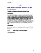
A multimeter can be used either as a voltmeter measuring voltage or an ammeter measuring current to use it as a:
Voltmeter
You must turn the dial to the left where there are various different levels of settings to measure voltage. You use only the two terminals for voltage, which are the common and V out terminals. The V out which is the positive terminal and the common, which is negative.
Ammeter
You must turn the dial to the right where again there is a range of current measuring settings. You use only the two terminals for voltage, which are the common and 10ADC terminals. The 10ADC, which is the positive terminal and the common, which is negative.
A voltmeter measure voltage in volts across a component and must be placed in parallel around the component under test. The correct name for voltage is potential difference.
Where an ammeter measures current in amperes flowing through the circuit the component under test and must be placed in the series, it can be placed any where in the circuit but must be in series and not parallel.
Variables
Independent
The independent variable I will be changing is the length of the piece of eureka wire.
Dependent
The dependant variables I will be measuring are the current and voltage of the eureka wire in order to find the resistance of it.
Controlled
The controlled variables I will be regulating are the voltage supply entering the wire, the cross sectional area of the wire therefore keeping the same number of atoms. Also the same piece of wire will be used for each experiment while also using all the apparatus.
Prediction
I predict that there will be a directly proportional relationship between the length and the resistance of the wire. This means the longer the wire, the higher the resistance. So therefore when a graph is drawn up I think that it will have relatively close correlation in there are no major anomalies. I believe this is because the longer the wire, the more free electrons there are in it, which will collide with other free electrons and the other particles making up the metal, also any impurities in the metal. Therefore, more energy is going to be lost through these excess collisions and this energy is wasted and lost mostly as heat.
Furthermore, doubling the length of the wire will result in double the resistance. This is because by doubling the length of the wire one is also doubling the amount of free electrons and therefore the amount collisions that will occur, thus doubling the amount of energy lost in these collisions.
Apparatus
1 Lab pack
6 Wires
4 Crocodile clips
2 Multimeters (1 voltmeter & 1 ammeter)
1 Variable resistor (Max 66Ω)
2 Meter rulers
2 Meter strip of eureka wire
Diagram
Safety
Safety is vital to this experiment as it can be very dangerous especially when dealing with hot wires and electricity, so it’s important that these rules are remembered.
In order to perform a safe experiment, keep the lab pack at a low voltage of 2V, so that overheating was minimised and also decrease the chance of short-circuiting the lab pack or the multimeters.
Always remember that when dealing with electricity to be careful not to apply water as this could also short circuit components.
Also remember that if you are moving the crocodile clips on the eureka wire or adjusting the multimeters then the lab pack will have to be turned off again to stop short-circuiting.
Method
The apparatus was collected and put together as listed below:
Two metre length of “eureka wire” (a metal alloy) wire was fixed to a 2 connected metre rulers. Next the lab pack was turned down to 2 volts an the 2 wires were inserted the positive wire was then connected to the 10ADC terminal in the ammeter which was set to 200mA then another wire was connected from the common terminal to the first crocodile clip which was clipped to the wire at the 0cm position on the metre rule, the second crocodile clip was clipped to 50cm position further on up the wire. A voltmeter set at 20V is the connected in series to the crocodile clips, the positive to the V out and the negative to the common. From the second crocodile clip a wire runs to the variable resistor on the side with only one terminal and another wire runs from the top terminal on the other side back to the negative terminal on the lab pack.
To perform the experiment the following steps were taken:
The lab pack was plugged in and the power supply turned on. The voltmeter and ammeter were checked to see if they were in the right positions, then voltage and current were then read off them, the results were recorded. The power supply was then turned off wile adjustments were being made (to avoid short-circuiting) and the second crocodile clip is moved to the next position 10cm up the eureka wire. The same process was repeated for every 10 cm from 50cm up to 150cm. The above steps are completed for each length and then the entire investigation is repeated 3 times to decrease the chance of inaccuracies from distorting the results.
Next when all the results were recorded in an organised table, which is shown in my results the resistance, had to calculated by using the formula R = V/I and the average resistance of all there repetitions was calculated and these results were placed into a table also shown in my results section. Now a graph has to be drawn up to show these results in order to agree or disagree with my initial hypothesis.
Results
On this page & the next there are 2 tables of results for the experiment on current & voltage of a piece of eureka wire due to its length.
On the next page is a table of results for the experiment on resistance of a piece of eureka wire due to its length, which also includes the average resistance as well as all 3 repetitions. Below that is a scatter graph of the results in the table you should look at the important factors like its correlation its gradient & the closeness of the points to the line of best fit.
In the graph we can see that there is an extremely close yet not perfect correlation. This shows that the resistance of the wire does proportionally rise with the length.
Conclusion
I now know that there is a directly proportional relationship between the length and the resistance of the wire. This means the longer the wire, the higher the resistance. As my prediction has stated and my results have proven the graph that has been drawn up has very close correlation, as there were no major anomalies.
This is because the longer the wire, the more free electrons there are in it, which will collide with other free electrons and the other particles making up the metal & also any impurities in the metal. Therefore, more energy is going to be lost through these excess collisions and this energy is wasted and lost mostly as heat. Also to prove the directly proportional relationship between the length & the resistance of the wire we can look at the percentage of change between the two.
If there is a 20% change in the length of the wire then there will also be a 20% change in resistance throughout the wire.
Length Resistance
50cms = 5.3Ω 10/50 X 100 = 20%
60cms = 6.5Ω 6.5 - 5.3/5.3 x 100 = 22.6%
100cms = 10.8Ω
One other thing, which will prove my prediction to be accurate, is the gradient of the graph slope and to find the gradient of anything you simply divide the rise by the run
Rise/Run
16.1 X 10 ÷ 150 = 1.093 or 1.1
This not only shows that the there is a relationship but also how closely accurate the my results as there is just over 1 ohm of resistance per centimetre of eureka wire.
Furthermore, doubling the length of the wire will result in double the resistance. This is because by doubling the length of the wire one is also doubling the amount of free electrons and therefore the amount collisions that will occur, thus doubling the amount of energy lost in these collisions.
Evaluation
Even though my results were extremely accurate and prove my prediction to be correct and are easily supported by my conclusion, I still believe that there were some factors that maybe made my results ever so slightly bias or in accurate, I have made a list of these problems & also a suggestion for each on how to improve them & the experiment as a whole.
The first thing is the temperature of the wire in which we were using, as the electricity pass through it the particles in it vibrated and caused an increase in temperature & a decrease in area in which the free electrons could pass by this would have surely varied the results even just slightly. I believe that if the wire didn’t heat up the results would be more accurate, so I think to stop this from happening the wire should be let to cool between each reading to ensure a regular temperature.
Another big point that would vary the results moderately would be the length of the wire. What I mean by this is as the crocodile clips were moved up the wire it is extremely hard to judge whether or not it was on the correct measurement as your eye isn’t as accurate enough to measure the length properly even with a meter stick attached. I think if there was a more accurate way of measuring the length of wire for instance an electronic measuring tape then the results would be more reliable.
The final point of error within the experiment is the multimeters. The multimeters are not accurate enough themselves as when both the voltage and current were recorded the last decimal place on the multimeters flickered up & down and continually varied a few decimal places this made it incredible difficult to know which was the correct result & if the wrong one were recorded the results would be incorrect. So I would suggest that a more accurate type of multimeters should be used or a setting with a greater degree of accuracy this would insure the results to be correct.
Despite these anomalous factors, my results still enabled me to find the relationship between length & resistance of a piece of eureka wire, also the results I obtained supported my predictions & were even accurate enough to support my conclusion. I think that if these three points were improved upon then the results would be a lot more reliable and would give a better understanding of the relationship between the length and resistance of a piece of eureka wire.