Method:
We are going to use a circuit that includes a 12v power pack on a d.c and a.c current, a variable resistor set at different currents, an ammeter, crocodile connecting clips, an iron core, a wire coil, paper clips and a light bulb which provides resistance when we are using just a few turns on a coil. We shall vary the length of the wire by changing it for different lengths but keeping the amount of coils and voltage the same. We will vary the amount of coils by adding them or removing them keeping the same length wire and voltage. We will vary the amount of volts using the variable resistor, but still keeping the same amount of coils and length of wire. To make sure that we get the right amount of volts we shall use an ammeter that indicates the number of volts, this also make the test fairer. After each test we will demagnetise the iron core by making it a.c before doing the next test in d.c. With each variable we will test it three times to get fair results, and we shall record the number of paper clips picked up each time. The number of paper clips picked up should be different for each variable test we do. The safety we need is general laboratory rules, and electrical safety. Electrical safety includes things like no bare wires and no short circuits. To keep it a fair test we will only change one variable at a time, and keep the others constant throughout the test. One factor we may not be able to control is a steady current, as it tends to rise and fall due to the power supply.
Circuit diagram:
Results:
Current Variable:
Number of Coils Variable:
Length of Wire Variable:
Graphs Of Results:
Conclusion:
These results prove that my prediction was correct that these three variables change the number of paper clips picked up. The more coils, the greater the voltage, and the longer the wire all resulted in the most amount of paper clips being picked up. My graphs show this as they all increase steadily. Andre Ampere invented the electromagnet in 1825 after several years of work by many people regarding the magnetic properties of current carrying wires. In 1819 Hans Christian Oersted performed an experiment to show that a wire carrying an electrical current could influence a nearby compass needle. The wire produces loops of magnetic field lines around it. Their direction can be determined by the right-hand screw rule. Imagine turning a screw so that it moves into a piece of wood. You have to turn it clockwise, and it will move forward. In analogy, the current represents the movement of the screw, and the resulting field line direction is the direction of the turning.
If a wire is wound into a coil, then the field lines add up in such a way as to produce a set of field lines that surround the coil in a similar way to those that surround a permanent bar magnet.
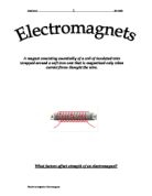
If further, a piece of soft iron is placed inside the coil, then the magnetic domains in the iron align with the field lines and they themselves serve as many little bar magnets in the iron, creating a powerful bar magnet for as long as the current is switched on. This is what we call an electromagnet.
Evaluation:
I believe all our results to be correct accept for last test which was the length of the wire. The anomalous results were the 1m wire test where the results where less than the 0.75m test. I think this may be due to a faulty wire as all the other results were fine. All our results were valid and all were done under our fair test guidelines. To make the test fairer I believe that we could have got a more accurate results with a more constant power supply as they power could dip as much as 0.2 volts. That was the most difficult problem was trying to do the test with a constant current. To improve the experiment I would try varying the core in which we used and try moving the core around inside the coil. This extra evidence would prove that the cutting of magnetic fields produces electricity.