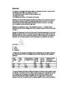
I will take Three measurements of the thicknesses of the wires at different points along the wire,
at the end the middle and the other end, and take an average, the wires thickenesses will be
measured using a micrometer i will then use this thickness to calculate the cross-sectional area of
the wire using the formula *Pi x (R x R) where R= the radius of the wire the radius is half the
diameter, and the diameter of course is the thickness of the wire so i will get the mean cross
sectional area throughout the wire. I will also take three measurements of the the ampage
flowing through the wire, i will take the measurement, turn the power supply off the prevent any
heat build up in the circuit wait for 10 seconds then take my measurements again this i will
repeat 3 times and take the mean average from these results. Also to keep heat down i will run
my experiment at a low voltage not too low to get a very small current but not too high to create
excessive heat. All the wires wil be keptthe same length which was decided at 60Cm.
Preliminary work was carried out to decide the best voltage and the best length to gain the
optimum Current.
Preliminary work.
Preliminary work is carried out to iron our any teething or unseen problems that might occur
during the proper experiment, if a problem occurs during preliminary work it does not matter
and usually you can easily see where you have gone wrong and remedy the problem, also i is
useful to find out what voltage we should run the experiment at and what length of wire we
should use.
* Pi is taken as 3.14.
Method
In order to carry out this investigation fairly and properly i will need the following apparatus:
6 Ni-crome wires of varying thicknesses. I am keeping the same material for each wire
thickness because wire material is a factor affecting resistance.
An Ammeter
A voltmeter
Power Supply
A Micrometer To accurately measure the thicknesses of the wires
A power supply unit which can control the amount of voltage delivered across my test circuit
because 240V is obviously a dangerous and excessive voltage.
Two clamp stands.
Connecting wires from the PSU to the crocodile clips
A ruler to measure the length of the wire. I will keep the length of all the wires the same, the
lengths of the wires will be measured down to 0.1 of a centimetre, this is because wire length is
a factor affecting resistance.
This is how my experiment will be set up.
Results
Following my plan here are the results that i obtained.
Thicknesses. (mm)
Size 1st 2nd 3rd Mean
1. 0.97 0.97 0.96 0.97
2. 0.73 0.73 0.73 0.73
3. 0.56 0.56 0.56 0.56
4. 0.46 0.46 0.46 0.46
5. 0.38 0.38 0.38 0.38
6. 0.33 0.32 0.31 0.32
Cross-Sectional Area (mm2) to 2 DP
1. 0.74
2. 0.42
3. 0.25
4. 0.17
5. 0.12
6. 0.08
All tests were carried out at 2.5 Volts
Ampage.
1st 2nd 3rd Mean
1. 1.17 1.20 1.23 1.2
2. 0.76 0.75 0.74 0.75
3. 0.52 0.51 0.55 0.53
4. 0.35 0.35 0.37 0.36
5. 0.24 0.22 0.23 0.23
6. 0.16 0.13 0.17 0.15
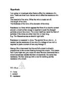
Resistance. Worked out using the formula V= I/R Where V is the voltage, I is the
current and R is the Resistance. so to work out Resistance i used R= I/V and
measured in Ohms.
1st 2nd 3rd Mean
1. 0.47 0.48 0.49 0.48
2. 0.30 0.30 0.30 0.30
3. 0.21 0.20 0.22 0.21
4. 0.14 0.14 0.15 0.14
5. 0.10 0.09 0.09 0.09
6. 0.06 0.05 0.06 0.06
Conclusion
From my results i can conclude that as the thickness of the wire increases in increments so the
resistance of the wire decreases. This is because as the thickness of the wire increases the
amount of space in the wire increases also therefore Electrons travelling through the wire have a
lesser chance of colliding with the stationary atoms. This goes with my hypothesis stated earlier,
which stated that as the thickness of the wire increases so the resistance decreases.
You can clearly see a smooth curve of points on my graph this shows that the two pieces of
data are negatively proportional but not directly, as one goes up the other goes down but not
always by the same amount this is because doubling the width of the wire does not double the
gaps between the atoms.
Evaluation
I think that by good use of preliminary work before we started the experiment proper helped
very much to iron out any problems such as the wire heating up and causing us to have
anomalous results, as a result we did not have any anomalous results therefore the experiment i
think can be judged as a success as it has proved my hypothesis, and the data shows it without
being compromised by anomalous results however this is of course not a perfect experiment to,
next time i would like to take more than the three readings to iron out any results which might
have been even slightly wrong, also the crocodile clips appeared corroded and did not
neccesarily provide the best contact with the wire, next time i could use points which are smaller
and give a much better contact with the wire, however i think that the results that i did take were
accurate discounting any unnavoidable equipment errors and shortfalls, by using the micrometer
to measure the thickness of the wire we got a very accurate and fool proof measurement that
wasn't open to the kind of guess work that would occur with use of a ruler, the Volt meters and
Ammeters were accurate enough at 0.01 of an amp and 0.01 of a volt we wouldn't want to go
any more accurate than that. One problem which might have adversely affected our results
which we noticed in the preliminary work but couldn't find a solution for was the fact that the
wires used had been coiled up for some time and therefore when tried to pull straight kept
coiling up, this arcing in the wire might have caused at small magnetic field thus losing some
energy and increasing resistance, this could be solved by keeping the wire tort for some time to
allow it to return to its natural state, however on the whole these things did not affect the results
and i think i was a success.
Matthew Towell
10WS