In a longer piece of wire, there would be more particles for the electrons to collide with and so the resistance would be greater. The relationship between wire length and resistance should be directly proportional. This is because in a wire twice the length, there would be twice as much particles and therefore on average twice as many collisions. Leading to twice as much heat lose.
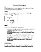
The resistance of a wire is calculated by measuring the current present in the circuit and the voltage across the wire. The formula is:
Voltage (V) = Current = (I) x Resistance (R)
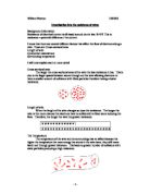
This also relates to Ohm’s Law. Which status that the current through a metallic conductor (for example, a wire) at a constant temperature
Is proportional to the potential difference (voltage). This means that the resistance of a metallic conductor remains constant, provided the temperature also remains constant. Also, the resistance of a metal increases as its temperature increases. This is because at higher temperature the electrons are moving more quickly, therefore increasing the chance of collisions with other particles.
Another equation for the resistance of a wire is:
R= pl/A where R= resistance in Ohms, p= receptivity of the wire in ohm-metres (this depends on temperature) L = length of the wire in metres, and A = cross sectional area of the wire in square metres. In the experiment, I will be using Constantan wire. This means that the receptivity is 49-ohm m (at 20oC).
Results table:
Observations:
We will observe the reading on the voltmeter change as we change the current to .3 A. we also observe a general increase in the voltage as the length of wire we use gets longer. The variable resistor will also be set at different positions for the different lengths of wire that we use.
To make sure our overall values are as accurate as possible we will repeat our readings 3 times and then take the mean resistance of the 3 readings. We will also be able to spot and
Analysis
Trends:
From the graph we can see one very clear trend, which is, as the length of the wire increases so does the resistance of it. Another, more significant thing is that it the increase is constant. This is indicating by the fact that the line drawn is a straight one. One may also note that the gradient of the line drawn is steady. There were no anomalies in this experiment
Conclusion:
I think that from my results I can safely say that my prediction was right. The resistance did change in proportion to the length. This is because as the length of the wire increased the electrons that made up the current had to travel through more of the fixed particles in the wire causing more collisions and therefore a higher resistance. We can work out what the receptivity of the wire should be from our results using the formula
Evaluation:
It is obvious from the formula that R/l is simply the gradient of the graph, therefore I feel that overall our results were quite accurate. This is can be seen when we look at the graph, which shows a straight line with all of the points apart from one being very close to or on that line. The one point that was not that close to the line was a slight anomaly, but it was only slight and did not effect the final gradient of the graph.
The accuracy for this experiment is very high. But as one can see this does not seem to be the case from looking at the graph. The reason for this could have been due to a number of different factors. Firstly the temperature of the wire was not necessarily 20oC when we conducted the experiment and the material of wire may not be as pure as it should have been. The main reason for this was probably due to the equipment that we used being inaccurate. This did not stop us from seeing the trend, though, because the equipment would have been out by a constant amount each time therefore there was a constant error. So the trends that were predicted in the plan still were shown.
Most errors in our experiment were encountered in the measuring of the wire. This is because it simply was not very practical to hold a piece of wire straight, whilst holding it next to a ruler and then trying to accurately fix crocodile clips to the right part on the wire. Also I do not feel that the crocodile clips were always fixed securely to the wire with a good connection. This also meant that they were easy to move about on the wire changing the length of it. Errors rarely occurred in the setting of the current and the reading of the voltage. It was just in the preparation area that they did occur. Another example of this is the wire was never totally straight when we started the experiment, which may also, as said earlier on, affect the resistance of it.
I do not think that doing any more results in our experiment would have made it any more accurate. I feel that the only way to make it more accurate would be to use a different method – perhaps were we had a bar that did not bend in place of the wire. We could even use a rheostat in place of the wire, because it is essentially a long coiled wire that is connected at different lengths to change the resistance of the circuit