Resistance is a constant, so even with a varying voltage the resistance will stay the same.
Resistance is referred to as ‘R’ in formulae.
Diagram
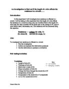
Equipment used:
- Three 1.5V batteries
- Thick Steel Wire
- Digital Ammeter
- Digital Voltmeter
- Variable Resistor
- Crocodile clips
- Ruler
This equipment was used because the digital voltmeter and ammeter are more accurate than their mechanical equivalents, the variable resistor was used to make sure the wire did not overheat due to the resistance (see more in the fair test section), and to make sure that I could still obtain accurate readings. The 1.5V batteries were used instead of a power pack, due to a lack of available equipment. The crocodile clips were used simply to connect and complete the circuit, and the wire length was the variable in this experiment (the properties were selected in the preliminary experiment, shown in the method). The ruler was used to measure the length of the wire.
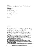
Method
The circuit shown in the above diagram was set up. Then, the wire was measured, and two crocodile clips were attached to the wire, where it was attached depended what length was being tested at that time. A voltage was set, by attaching 1, 2 or 3 batteries to the circuit. The switch was then pressed and the current and voltage were taken down. From this, the resistance in ohms (Ω) could be calculated, as I know that R = V / I (a special law). Then the readings were taken for the rest of the lengths and voltages.
The ranges and measurements taken: the voltage will be taken, in volts (V) and the current will be taken, in amps (I). This is because these to figures are needed to work out the resistance, in ohms (Ω).
The length of the wire will be taken, in centimetres (cm), because I need a unit with which to associate with length. I will go from 20cm, increasing by 10cm until I reach 100cm, because I feel this a more than adequate range which will produce many results.
The voltage I will have from the batteries will vary from 1.5V, to 3V, to 4.5V. This is so that I will have repeat results.
How I made sure the experiment was safe: the wire was not touched immediately after each result was taken down, as the wire might have been very hot and could have caused a burn. A variable resistor was used to make sure that the wire did not over heat.
How I made sure the test was fair: regular time intervals were taken between each experiment, to allow the wire to cool, to make sure that heat wasn’t affecting the experiment. The same piece of wire was used, with the same thickness and the same material, to ensure that length was the only variable. The variable resistor was kept at the same resistance, and the same power supply was used throughout the experiment. Only one variable will be changed at a time, so that any changes can be attributed to that.
Other variables that could have changed: the thickness of the wire, the material of the wire and different temperatures.
I only changed the length and none of the other variables because the length was the easiest to change, simply because all that was needed to alter the length was to move the crocodile clip, and so that, as stated above, that any changes in the experiment can be attributed to a single factor.
Results
See graph A, in appendix. The graph shows the relationship between length of wire and resistance. The graph shows me that as the length of the wire increases, the resistance increases proportionally. From my graph, I can tell that I have 2 obvious anomalies. I can attribute these to a faulty reading, because the ammeter was fluctuating, or to the incorrect measurement of length.
There is a pattern in the graph. If you were to double the length, the resistance would double accordingly.
The results table shows me that as the length of wire increases, so does the resistance.
From my graph, I can make new predictions. If the length of wire was 110 cm, I predict that the resistance would be approximately 7.5 ohms. I predicted this by carrying on the line of best fit.
Conclusion
From my results, I can conclude that my hypothesis was correct, and from my graph I can conclude that all the results agree with my hypothesis.
Discussion
I know that the movements of electrons is inhibited in a wire if there is not enough space for them to flow through, and this is called resistance. I know that a higher voltage is needed to push the current though a circuit.
The resistance in a circuit can be calculated by R = V / I.
Evaluation