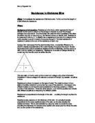
Electrons give energy to atoms in a conductor (in our case the Nichrome wire,) by colliding with them. This is shown below in a diagram.
Resistance of the wire will increase as the length of the wire increases because the longer the piece of wire, the more atoms and free electrons there are, and there will be more collisions between the atoms and the electrons, compared to a small piece of wire. This means that some of the energy will be lost, so the resistance increases. Electric current is the movement of electrons through a conductor. In this experiment a metal wire (Nichrome will be the conductor). So when resistance is high, conductivity is low. Metals such as Nichrome conduct electricity well because the atoms in them do not hold on to their electrons very well. Free electrons are created, which carry a negative charge, to jump along the lines of atoms in a wire, which are in a lattice structure. Resistance is when these electrons, which flow towards the positive, collide with other atoms; they transfer some of their kinetic energy. This transfer on collision is what causes resistance. So, if we double the length of a wire, the number of atoms in the wire doubles. This increases the number of collisions and energy transferred twice, so twice the amount of energy is required. This means the resistance is doubled. I have a diagram below showing this.
The property of the material that restricts this movement is known as the resistance of the conductor. For a metallic conductor at a constant temperature, the current varies linearly with the voltage-This is known as Ohm’s law. That is, the ratio of the potential difference V to the current I is a constant for any conductor, and is known as its resistance R. It is important to realise that Ohm’s law only holds if the temperature is kept constant.
My prediction graph is a straight line through the origin because I believe that the resistance will be directly proportional to the length of the wire, and my reasons for explaining this are above.
Apparatus required
- Power pack
- Wire for power pack
- 200cm of Nichrome wire
- Crocodile clips
- Voltmeter
- Ammeter
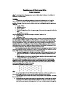
Diagram of apparatus
Method
1 We will set the apparatus up as shown in the diagram above.
2 We will measure out our designated amount of wire, and wrap any excess wire around the crocodile clips-in this case 20cm and we will increase the length each time by 5cm up to a maximum length of 60cm.
3 We will then switch on the power pack and set the current to 0.25 amps. We will do this by moving the variable resistor and stopping it when the ammeter shows 0.25amps.
4 We will then record the voltage shown on the voltmeter.
5 We will repeat the above for the different lengths of wire.
6 When we have recorded the voltages for each length of wire, we will use Ohm’s law to work out the resistance.
5 To ensure that our results are correct, we will repeat the above experiment using the same lengths of wire, but setting the current at 0.5amps and then 0.75amps. We will repeat the above for each one of these currents and record our results and use Ohm’s law to find out the resistance.
The instrument that we will use to measure the independent variable is a ruler.
The instrument that we use to measure the dependent variable is a voltmeter, and we will then use the voltage and current figures in our Ohm’s law equation to work out the resistance of each piece of wire.
Results Strategy
We will use voltage to measure the resistance of the wire. I have decided that the range of our independent variable should be between 20cm and 60cm in intervals of 5cm. I have decided this because most groups are measuring between 0cm and 60 cm in intervals of 10cm. I decided to measure between these to points to make sure that we were not simply copying what another group was doing. I also decided to measure in 5cm intervals because I thought that it would be more accurate for our graph and be a clearer reflection of our results. It would also show us more clearly if we had any anomalous results. I have also decided to conduct the experiment at 0.50Amps and 0.75Amps. I have done this to ensure that my results are concordance and that they are reliable because they have been repeated at different currents. I am also going to plot graphs for each current. This will show me clearly if I have any anomalous results and it will also show me my results in an accessible form. The graph’s axis will be the same as my prediction graph.
Here is table of results that I will record my results in. I will have 3 tables of results, one for each current.
Fair Test
To ensure that I am conducting a fair test, I have decided to take a number of measures to ensure that this occurs. I am going to use a ruler to measure the Nichrome wire and ensure that it is the correct length. I am also going to try and ensure that the current is within 0.01Amps of the desired current. I will also ensure that the thickness of the wire stays constant for each length and current. I will also make sure that I am using the same wire for each length, as a different wire might cause distortion of results. I shall also ensure that the designated current passing through the wire will not change until all the lengths of wire have been tested and the voltages recorded, then shall we increase/decrease the current to the desired figure. I will also try and use the same equipment for each current because any change of equipment might cause a distortion of results.
Safety Considerations
In doing this experiment, we must take many safety considerations into hand. We must try to keep the current low enough to avoid the heating effect, which may burn us or cause damage to surrounding objects. We must also not touch the wire once the power pack is turned on, because we do not know if the wire is hot or not. We must also avoid the wire coming into contact with any water on benches, as water is a good conductor, and this could be potentially dangerous.
Table of results
Here are our results for the current at 0.25Amps.
Here are our results for the current at 0.50Amps.
Here are our results for the current at 0.75Amps.
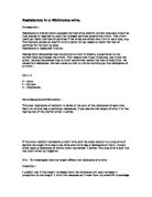
Graphs
I decided to present my results in graph form, as this would be the easiest and most accessible way to access the information. I plotted my points, and drew a line of best fit between them. I discovered that my line of best fit went through the origin. This meant that my results were directly proportional-as one rose so did the other. To ensure that they were directly proportional I found the gradient of each line. I discovered when I used the equation,
Y=Gradient
This meant that if I multiplied the gradient with any number on the axis, it would automatically tell me the corresponding number on the Y-axis. This showed me that my results were directly proportional.
Conclusion
In conclusion, I can say that both my predictions are correct. As we increased the length of the wire, the resistance increased, and as shown in my graph, resistance is directly proportional to length. I also noticed that as the length of the wire was increased, the voltage increased. I also noticed that for each of the currents, 0.25Amps, 0.5Amps and 0.75Amps, their resistances were very similar. This backs up my results and ensures that they are reliable. I can now state that as we increase the length of Nichrome wire, the resistance increases, and as we decrease the length, the resistance decreases. I can also state that resistance is directly proportional to length. To explain this we must look at Ohm’s law. Resistance of the wire will increase as the length of the wire increases because the longer the piece of wire, the more atoms and free electrons there are, and there will be more collisions between the atoms and the electrons, compared to a small piece of wire. This means that some of the energy will be lost, so the resistance increases. Electric current is the movement of electrons through a conductor. In this experiment a metal wire (Nichrome will be the conductor). So when resistance is high, conductivity is low. Metals such as Nichrome conduct electricity well because the atoms in them do not hold on to their electrons very well. Free electrons are created, which carry a negative charge, to jump along the lines of atoms in a wire, which are in a lattice structure. Resistance is when these electrons, which flow towards the positive, collide with other atoms; they transfer some of their kinetic energy. This transfer on collision is what causes resistance. So, if we double the length of a wire, the number of atoms in the wire doubles. This increases the number of collisions and energy transferred twice, so twice the amount of energy is required. This means the resistance is doubled. I have a diagram below showing this.
Metals, (such as the Nichrome wire that we are using) contain a sea of free electrons, which are negatively charged and flow throughout the metal. The resistance of a conductor depends on two things
1 Its dimensions.
2 The material of which it is made.
A good conducting material has more free electrons than a poorer one, and if these electrons can flow through the material easily, then the resistance is lower.
The property of the material that restricts this movement is known as the resistance of the conductor. For a metallic conductor at a constant temperature, the current varies linearly with the voltage-This is known as Ohm’s law. That is, the ratio of the potential difference V to the current I is a constant for any conductor, and is known as its resistance R. It is important to realise that Ohm’s law only holds if the temperature is kept constant.
Evaluation
If I were carrying out this experiment again, I would make a number of changes.
1 I would pre-measure and cut pieces of wire for the desired length.
2 I would start the lengths of the wire at 5cm to ensure a more accurate result and to see any anomalous results clearly.
3 The crocodile clips and the connecting leads could have affected the fairness of the experiment. They are a different type of metal from the Nichrome wire and may have different properties and therefore different resistance. Therefore the resistance of the Nichrome wire that we worked out was slightly more than it actually was. To solve this problem, I would have found out the resistance of the connecting leads and crocodile clips before each experiment and minus it from the overall resistance of the Nichrome wire plus the connecting leads plus the crocodile clips.
In doing this experiment I encountered two main problems. One was measuring the wire accurately enough and the other was adjusting the variable resistor to make sure that the current was correct, which was very difficult considering that the current could fluctuate by up to 0.05amps. To remedy this, I would pre-cut and pre-measure the wire that I was going to use in the experiment. I would try to keep the current constant by using an advanced digital variable resistor, which would stop the current from fluctuating as much.
When I drew my graphs, I encountered some strange measurements. At 0.25Amps I noticed that 50cm was slightly outside my line of best fit. At 0.50Amps, I noticed that 50cm was also slightly outside my line of best fit. Also at 0.75Amps, I noticed 60cm was slightly outside my line of best fit. I can put these results down to experimental error-when we were measuring the wire and wrapping it around the crocodile clips; it would have been very easy to misjudge the length and have the wire a few centimetres longer than it was supposed to be.
I could now carry out further experiments related to the resistance in a wire and see if the following factors would make any difference in the resistance of a wire.
Wire width: I think that if the wire width is increased the resistance will decrease. This is because of the increase in the space for the electrons to travel through. Due to this increased space between the atoms there should be less collisions.
Temperature: I think that if the wire is heated up the atoms in the wire will start to vibrate because of their increase in energy. This causes more collisions between the electrons and the atoms as the atoms are moving into the path of the electrons. This increase in collisions means that there will be an increase in resistance.
Material: I think that the type of material of the wire will affect the amount of free electrons, which are able to flow through that wire. This is because the number of electrons depends on the amount of electrons in the outer energy shell of the atoms, so if there are more or larger atoms then there must be more electrons available. If the material has a high number of atoms there will be high numbers of electrons causing a lower resistance because of the increase in the number of electrons. Also if the atoms in the material are closely packed then the electrons will have more frequent collisions and the resistance will increase