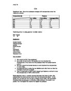
On the lower surface of the airfoil, there is a stagnation point near the leading edge, where Cp = 1.0, and the flow accelerates thereafter. When the two pressure coefficient distributions are plotted versus chord-wise location, (x/c), the area between the two curves is a measure of the normal force coefficient on the airfoil and hence of the airfoil lift coefficient.
As the angle of attack is increased, the suction peak on the upper surface grows larger and the adverse pressure gradient becomes larger as well. At some value of angle of attack, the adverse pressure gradient on the airfoil upper surface becomes strong enough that the boundary layer separates from that surface. When this happens the boundary layer leaves the upper surface and the oncoming free stream flow perceives a radically modified airfoil shape. The resulting effect is termed airfoil (or wing) stall, and the included area between the upper and lower pressure distribution curves collapses. The presence of stall was evident in the force measurements on the airfoil that were conducted in a previous laboratory.
Fig 1: shows pressure distribution
over a symmetrical airfoil.
The trends explained above present the basics of lift. The lift force is the force perpendicular to the direction of flow. For small angles of attack it is proportional to the Normal force. When the angle of attack is increased the intensity of lift also increases making the plane fly higher until a critical angle is reached, beyond this angle the airflow on the upper surface separates and drag increases causing stall, therefore preventing further lift, this causes the plane to descend.
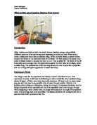
Measuring Devices to be used are Pressure Taps- The surface pressure distribution on an airfoil will be measured by means of 14 static pressure taps. These are small holes on the surface of the model that are connected to stainless steel tubes within the model and then to plastic tubing. The pressure taps on the airfoil are located on the upper and lower surfaces in the chord-wise direction at mid-span. The plastic tubing from these orifices is connected to separate monometers.
The local velocity in the boundary layer on the ceiling of the wind tunnel will be measured. Since the static pressure is constant throughout the ceiling boundary layer, a single static tap on the ceiling at the measurement station will yield the local static pressure anywhere in the boundary layer at that station.
This diagram shows the Airflow around the airfoil in a wind tunnel.
It shows how the airflow is distorted around the airfoil.
Theory
The pressure coefficient is defined by:
Cp = (p-p∞)/( 1/2 pU² )
Where p∞ is the static pressure in the free stream and U is the velocity.
The coefficients may be determined directly from the monometer reading as follows:
Cp = (h-hs) / (ha-hs)
Where h is the reading for the tapping, hs is the static pressure in the tunnel and ha is the atmospheric pressure.
The tunnel speed is determined using:
1/2pU² =ρmg(ha-hs)sinө (m/s)
Where ρm is the density of the manometer fluid (830 kg/m³), p is the density of the air (1.23 kg/m³) and ө (23º) is the inclination of the manometer to the horizontal.
The lift coefficient CL is defined by
CL= L/(1/2pU²c)
Also given by
CL≈ CN = - ∫ Cp d(x/c)
The lift coefficient CL, can be determined by measuring the area enclosed by the curve of Cp against x/c.
This can be done by counting the squares between the curve and the axis or using the trapezium rule.
Reynolds number is defined by:
RE = Uc/V
Where U is the free stream velocity, V is the kinematics velocity and c is the length of the chord.
Given by
V= µ /p
Where µ is the coefficient of viscosity and p is the density of the fluid.
For incompressible flow, and fixed wing geometry, we can see that for a fixed coefficient of lift CL, the lift is directly proportional to the square of the speed. This means that the faster the wing moves through the fluid, the more lift is generated. That is why an airplane has to pick up speed down the runway before it is able to takeoff. In order to takeoff, the wings (the entire vehicle) must produce more lift than the total gross weight of the aircraft (gross weight is the absolute total weight, i.e., including passengers, luggage, fuel, etc.). When the airplane is cruising at a constant altitude, the lift only has to balance, not exceed, the weight.
Where L is the lift, q∞ is the dynamic pressure, and S is some reference area. Remember, dimensionless coefficients such as cl enable us to scale experimental results from sub–scale models to full–scale vehicles. Another thing to note is by writing Eq. (3) like,