2 - Dismantling
Again take notes of everything - your brain is worse than you think. Solder off all connections of the coil stack, bend the 2 metal pieces back to exactly straight form, take carefully the coil stack off. Now the fixings of the capacitor block are accessible and can be taken off. After removing the cap block the 3 screws of the tuning cap are visible. Then I took off all the other parts on the upper side (except the mains jumper board) and all capacitors under the chassis. I also dismantled the feedback cap and the tuning shaft (middle). I left the band switch in place.
3 - Sanding and painting the chassis
With sand paper I took off all rust. Covered all visible parts with paper and stuffed the holes in the chassis with paper to protect all parts remaining under the chassis.
The rust was just on the surface, no deep holes. So I decided to skip a rust proof filler and painted the chassis parts with 3 thin layers of silver spray (car wheel spray).Always apply thin layers to avoid teardrops.
4 - Restoring the block capacitor
My opinion: In pre war sets there should be no modern components visible, not even under the chassis.
Bend back the metal flaps. Heatup the block in the oven to 75 degrees Celsius. Put some old newspapers under the block to avoid the mass in your wifes oven. When the block is warm enough you can pull out the inerts. Under the hard paper (Pertinax) there is a layer of tar and then the capacitor rolls. Take out everything but leave the cardboard that isolates the the walls inside of the metal box..
Use modern replacement caps rated as original or higher voltage. Inside this box you can use radial (rectangular shaped) parts. I used (11) caps of 1 uF /630 volts DC each. For the 4uF +4uF sections electrolytic caps are also possible. The 0.1uF section is connected to mains - thats why I used a capacitor rated for 250 volts AC with all the VDE, UL ... safety signs on it. The row of 10 caps is glued together and fits exactly into the old box. Connect the new caps to the old terminals. Stuff the empty room with synthetic padding wool to avoid rattle. Don't use the tar again. I don't seal it with 2 -compo resin to allow coming generations change the caps again if needed. After testing all sections close the metal flaps.
5 - Restoring the (4) tar sealed discrete capacitors
Heat them up in the oven to 75 degrees Celsius . Pull out the inerts. Use modern caps (axial types) of the same or higher voltage if available that go into the old tubes of glass or crdboard. The old capacity unit "cm" is approx. 1 pF. All (4) old caps were rated 1500 V ~ . If no replacement of the same or higher voltage is available you really have to understand the schematic what voltage is applied. These tuned radio frequency sets (TRF) with feedback can produce higher voltages than the plate voltage when oszillating. If the wires of the new caps are too short, I re-use the old wires. I also re-use the old insulation hoses.
I filled the old tubes with new axial type caps:
for the 60 cm/pF ...two ceramic caps of 120 pF/500 V= each in series (in order to give exactly 60pF/1000V= /as modern part not available)
for the 150 cm/pF ...a ceramic cap 150 pF/2kV=
for the 4000cm/4nF ...a 3.9 nF /630 V= Philips axial PP type ( I did't feel very comfortable with this one, so I tested this part with 450 V~ overnight - and it survived)
for the 5000cm/5nF ..a 4.7 nF / 1500 V= axial PP type
If the mains plug is inserted the bad way the chassis has mains potential ! The 4nF and 5nF caps connect the chassis to the RF ground connector and antenna connector. So these parts are safety relevant and must withstand mains voltage when ground connector is grounded or antenna is touched with hands.
These static caps don't have "+" and "-" like electrolytic caps. Most static caps have a marking on one side. This marks the outer layer of both foils and should be connected towards the chassis. Connecting the wrong way can produce hum in some cases.
6 - Loose grid caps or tube sockets
Unsolder all wires of the socket. Use vacuum pump to remove the liquid solder. Sometimes the wire on top of the tube is broken, then carefully file off a bit from the glass and solder an extension wire. I use 2 component glue that can withstand higher temperatures. After the glue is hardened solder the wire connection.
7 - Missing shielding laquer of tubes
The shielding laquer of these old tubes is often very brittle or already fallen off. There is a wire between glass and socket connecting the shielding laquer to the shield pin. I used a mixture of Zappon laquer and graphite powder. That worked well but the surface is a bit rough and the colour is grey. Later I learned there should be electrically leading laquer spray available from "Contact Chemie". I have not yet tested that.
8 - Revision of tuning capacitor
The tuning cap is operated indirectly from the tuning knob/shaft. The small double spring wheel on the tuning shaft grabs the large wheel (= dial) from front and rear. I cleaned and lubrified the tuning cap with Ballistol non-sticking weapon oil. After installing the cap it still did not work properly because the distance of both shafts was a bit to large. The only way of reducing the distance was to press down a bit the chassis where tuning caps sits. After this precedure the tuning worked perfectly smooth now.
9 - Repair of filament resistor
When I tried to repair the loose wire by moving the brass clamp the clamp broke. And 2 other clamps had small cracks. Very bad wartime material. I decided to re-manufacure the clamps from pieces of brass 5 x 0.5 x 100 mm all handmade. I could the reuse the old resistor wire and fix the clamps in the right position. The resistors value is 1100 + 400 ohms/ 0.05 amps and a separate section of 150 ohms/ 0.1 amps.
10 - Cleaning and testing all parts before reassembling
Now you find out why it was important taking notes!
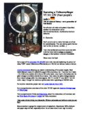
Restoring a Volksempfänger VE 301 GW (Nazi people's radio)
This is a piece of history - not a promotion of Nazi ideas!!
For all other old radio enthusiasts I described detailed the restauration of the electronics/mechanics. Additions/corrections welcome.
0 - Remarks
Don't connet a set to mains that was out of use for years/decades- You can destroy parts that are hard to find (x-former, rectifier...)
This x-formerless sets and even some sets with x-former have mains voltage on chassis !! Danger !! Use isolation x-former if available
Never short the fuse!
Get a copy of the and a tube manual explaining the pinout of tubes."GW" means Gleichstrom/Wechselstrom = DC/AC set without mains x-former.
allowing you easier understanding of the power supply. Each tube's filament needs 55 volts/0.05 amps=1100 ohms when hot. There are the 3 tubes + the 1100 ohms resistor all in line at 220 volts mains. Like most x-formeless sets the plate voltage is rectified directly from mains. That means the plate voltage depends from mains voltage (after the choke approx. 205 V = at 230 V~ and 100 V = at 110 volts~ resp.) You get the maximum performace when operating at 220/230 volts.
For another restoration project see my .
For a comprehensive overview of the other VE 301 types see .or
Very comprehensive FAQs see , about the restauration of American sets see .or car radio restoration
Take notes of everything you dismantle. Without schematic and without notes you are lost!
Recommanded: a gauge for measurement of capacitors. Experience: 99% of all pre-war paper caps are bad, especially when the set was stored under high humidity conditions and not in use for several years. Ceramic caps usually have no problem if not mechanically broken.
There are 4 discrete caps and 1 block capacitor (combination of 4+4+2+1+0.1 uF in one box) These old caps are wound of 2aluminum foils with paper (soaked with stearine) as dielectric, all sealed with tar. By attracting humidity their capacitance value becomes 5 or 10 times higher than nominal. In the same way as their capacitiy grows - their insulation capability goes to zero. These tar sealed caps are definitely not made to last for the 1000 years Reich. In professional or military equipment you can find glass sealed caps in tubes of ceramic material - OK after decades.
There are different ways restoring an old radio set - following my preferred way applicable similarly to other pre war sets.
1- Diagnosis
The bakelite case was in perfect condtion - just needed cleaning. I cleaned the knobs and details of the eagle with an old toothbrush. The speaker cloth was original and clean but a bit loose, needing a few of glue. The knobs were perfect - except one screw that was too long. (MAINS VOLTAGE !) If the screws of the knobs are rusted and hard to unscrew use weapon oil or "Caramba" and let it soak over night.
Taking off the original backside cardboard showed the chassis. Soldering off the speker wires ( note the colours). When taking out the chassis - take care of the dial. The dial goes under the speaker. All parts were there, but the chassis was pretty rusted on the upper side. I decided to dismantle all parts and repaint the chassis. If you don't want to repaint the chassis you have to take off the stack of coils because the capacitor block is fixed under the coils. On top of the VL1 tube the grid cap was loose, the VC1 was missing some shielding laqueer. The filament resistor had a loose wire, the mechanics of the tuning capacitor did not work well, choke (smoothing coil) and coupling x-former were OK, the 2M resisitor and 100pF ceramic capacitor under the grid connector of VC1 were OK. the block capacitor was a few blown up and there was 1 additional modern 4uF capacitor installed (as smoothing help). The socket of VC 1 is shock proof suspended with 3 pieces of felt, the felt was eaten up by insects. After restoring the original caps this additionsal 4 uF cap must go out. Each rectifier tube can only feed a certain load, a larger cap (than original used) would smoothen better but stress the rectifier tube.
2 - Dismantling
Again take notes of everything - your brain is worse than you think. Solder off all connections of the coil stack, bend the 2 metal pieces back to exactly straight form, take carefully the coil stack off. Now the fixings of the capacitor block are accessible and can be taken off. After removing the cap block the 3 screws of the tuning cap are visible. Then I took off all the other parts on the upper side (except the mains jumper board) and all capacitors under the chassis. I also dismantled the feedback cap and the tuning shaft (middle). I left the band switch in place.
3 - Sanding and painting the chassis
With sand paper I took off all rust. Covered all visible parts with paper and stuffed the holes in the chassis with paper to protect all parts remaining under the chassis.
The rust was just on the surface, no deep holes. So I decided to skip a rust proof filler and painted the chassis parts with 3 thin layers of silver spray (car wheel spray).Always apply thin layers to avoid teardrops.
4 - Restoring the block capacitor
My opinion: In pre war sets there should be no modern components visible, not even under the chassis.
Bend back the metal flaps. Heatup the block in the oven to 75 degrees Celsius. Put some old newspapers under the block to avoid the mass in your wifes oven. When the block is warm enough you can pull out the inerts. Under the hard paper (Pertinax) there is a layer of tar and then the capacitor rolls. Take out everything but leave the cardboard that isolates the the walls inside of the metal box..
Use modern replacement caps rated as original or higher voltage. Inside this box you can use radial (rectangular shaped) parts. I used (11) caps of 1 uF /630 volts DC each. For the 4uF +4uF sections electrolytic caps are also possible. The 0.1uF section is connected to mains - thats why I used a capacitor rated for 250 volts AC with all the VDE, UL ... safety signs on it. The row of 10 caps is glued together and fits exactly into the old box. Connect the new caps to the old terminals. Stuff the empty room with synthetic padding wool to avoid rattle. Don't use the tar again. I don't seal it with 2 -compo resin to allow coming generations change the caps again if needed. After testing all sections close the metal flaps.
5 - Restoring the (4) tar sealed discrete capacitors
Heat them up in the oven to 75 degrees Celsius . Pull out the inerts. Use modern caps (axial types) of the same or higher voltage if available that go into the old tubes of glass or crdboard. The old capacity unit "cm" is approx. 1 pF. All (4) old caps were rated 1500 V ~ . If no replacement of the same or higher voltage is available you really have to understand the schematic what voltage is applied. These tuned radio frequency sets (TRF) with feedback can produce higher voltages than the plate voltage when oszillating. If the wires of the new caps are too short, I re-use the old wires. I also re-use the old insulation hoses.
I filled the old tubes with new axial type caps:
for the 60 cm/pF ...two ceramic caps of 120 pF/500 V= each in series (in order to give exactly 60pF/1000V= /as modern part not available)
for the 150 cm/pF ...a ceramic cap 150 pF/2kV=
for the 4000cm/4nF ...a 3.9 nF /630 V= Philips axial PP type ( I did't feel very comfortable with this one, so I tested this part with 450 V~ overnight - and it survived)
for the 5000cm/5nF ..a 4.7 nF / 1500 V= axial PP type
If the mains plug is inserted the bad way the chassis has mains potential ! The 4nF and 5nF caps connect the chassis to the RF ground connector and antenna connector. So these parts are safety relevant and must withstand mains voltage when ground connector is grounded or antenna is touched with hands.
These static caps don't have "+" and "-" like electrolytic caps. Most static caps have a marking on one side. This marks the outer layer of both foils and should be connected towards the chassis. Connecting the wrong way can produce hum in some cases.
6 - Loose grid caps or tube sockets
Unsolder all wires of the socket. Use vacuum pump to remove the liquid solder. Sometimes the wire on top of the tube is broken, then carefully file off a bit from the glass and solder an extension wire. I use 2 component glue that can withstand higher temperatures. After the glue is hardened solder the wire connection.
7 - Missing shielding laquer of tubes
The shielding laquer of these old tubes is often very brittle or already fallen off. There is a wire between glass and socket connecting the shielding laquer to the shield pin. I used a mixture of Zappon laquer and graphite powder. That worked well but the surface is a bit rough and the colour is grey. Later I learned there should be electrically leading laquer spray available from "Contact Chemie". I have not yet tested that.
8 - Revision of tuning capacitor
The tuning cap is operated indirectly from the tuning knob/shaft. The small double spring wheel on the tuning shaft grabs the large wheel (= dial) from front and rear. I cleaned and lubrified the tuning cap with Ballistol non-sticking weapon oil. After installing the cap it still did not work properly because the distance of both shafts was a bit to large. The only way of reducing the distance was to press down a bit the chassis where tuning caps sits. After this precedure the tuning worked perfectly smooth now.
9 - Repair of filament resistor
When I tried to repair the loose wire by moving the brass clamp the clamp broke. And 2 other clamps had small cracks. Very bad wartime material. I decided to re-manufacure the clamps from pieces of brass 5 x 0.5 x 100 mm all handmade. I could the reuse the old resistor wire and fix the clamps in the right position. The resistors value is 1100 + 400 ohms/ 0.05 amps and a separate section of 150 ohms/ 0.1 amps.
10 - Cleaning and testing all parts before reassembling
Now you find out why it was important taking notes!