Introduction
The assignment investigates voltages, phase angles and power in AC reactive circuits using phasor diagrams, impedance triangles and calculations.
Part One – Laboratory Exercise
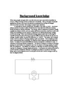
Circuit A
Value of components in the circuit
R = 470 Ω
L = 100 mH
Using a multimeter the following voltages were measured:
VR = 1.43v
VL = 2.17v
VS = 2.89v
The circuit was then connected to an oscilloscope so that one channel displays VR and the other VL. The readings taken are shown in diagram 1, they show that the Phase shift is approximately 90°. They also show the VL is leading and VR is lagging.
The frequency was then changed to 2 kHz the see how this effects the results and it was found that as the frequency is increased VR decreases and the Peak to Peak value of VL increases, the opposite occurs when the frequency is decreased. The readings taken when the frequency was at 2kHz is shown in diagram 2.
Circuit B
Value of components in the circuit
R = 470 Ω
C = 1μF
Using a multimeter the following voltages were measured:
VC = 0.78v
VL = 2.38v
VS = 2.54v
The circuit was then connected to an oscilloscope so that one channel displays VC and the other VR. The readings taken are shown in diagram 3, they show that the Phase shift is approximately 90°. They also show the VR is leading and VC is lagging.
The frequency was then changed to 2 kHz the see how this effects the results and it was found that as the frequency is increased VR decreases and the Peak to Peak value of VC increases, the opposite occurs when the frequency is decreased. The readings taken when the frequency was at 2kHz is shown in diagram 4.
Part Two – Practical Calculations
2.1)
Phasor diagram for Circuit A
Scale: 1v = 2cm
Phasor diagram for Circuit B
Scale: 1v = 2cm
The phasor diagram for Circuit A verifies that VL is leading VR.
The phasor diagram for Circuit B verifies that VC is lagging VR.
You are unable to get an exact scale for the diagrams as a ruler was used. VL is slightly out as there is resistance on the inductor, this means angle φ would not be exactly 90°.
2.2) – Using ohms law calculate the current in each circuit.
Circuit A Circuit B
R = 470Ω R = 470Ω
VR = 1.43v VR = 2.38v
I = = = 3.04 mA I = = = 5.06 mA
2.3) – Calculate XL, XC and Z for each circuit by two methods.
Circuit A
-
XL = = = 714Ω
b) XL = 2.π.f.l = 2xπx1000x100x10 = 628Ω
Circuit B
-
XC = = = 154Ω
-
XC = = = 159Ω
Results Table and comparisons
2.4) Draw impedance triangles for both circuits and use them to determine the phase angle (Φ) of each circuit.
Circuit A
Z = 784Ω Scale: 1cm = 100Ω
XL = 628Ω
R = 470Ω
Φ = TAN-1
Φ = TAN-1
Φ = 53°
Circuit B
Z = 496Ω Scale: 1cm = 100Ω
XC = 159Ω
R = 470Ω
Φ = TAN-1
Φ = TAN-1
Φ = -33°
2.5) Using the phase angle to calculate the power factor of the circuit, then calculate the power in the circuit.
Circuit A
Power factor = cos (Φ)
Power factor = cos (53)
Power factor = 0.60
Power = VS x I x power factor
Power = 2.89 x 3.04 x 0.60
Power = 5.27 watts
Circuit B
Power factor = cos (Φ)
Power factor = cos (-33)
Power factor = 0.83
Power = VS x I x power factor
Power = 2.54 x 5.06 x 0.83
Power = 10.7 watts
Part Three – Theoretical Calculation
-
A coil has a resistance of 12Ω and inductance of 15.9mH, connected across a 240v 50Hz supply
- Calculate the reactance of the inductance:
XL = 2.π.f.l
XL = 2 x π x 50 x 15.9x10
XL = 4.995 Ω
XL = 5 Ω
- Calculate the impedance of the coil: