The resistance of a wire depends on its size, material, and shape:
- Length – the longer the wire, the higher its resistance
- Thickness – the thinner the wire, the greater the resistance.
- The resistance of a wire also depends on the material it is made of
I have tested four different types of metals and experimented with different lengths. I have decided - from my results - that for my main experiment I will be using a wire which is made up of the material constantan.
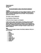
I will be using the constantan at a thickness of 28swag throughout the experiment. I found that when I used constantan at 32swag, it burned a lot easier then the constantan at 28swag.
I will be testing the wire at five different lengths- 10cm, 20cm, 30cm, 40cm, and 50cm. I found that this will give me a good, wide spread of results, and give me a clear idea of the pattern.
PREDICTION
I predict that as the length of the wire increases, the resistance will increase. I predict that the voltage readings on the voltmeter will increase as the length of wire increases, and the current reading on the ammeter will decrease. I predict this because as the length increases so will the resistance, therefore the voltage will increase and the current will decrease because it will become increasingly harder for the electrons to flow through the lengthening wire.
FAIR TEST
To ensure a fair test, the experiment will need to be repeated 3 times for each length. If any obvious anomalous results occur during the experiment, I will repeat the experiment until the results are reliable. The following experimental conditions need to be kept constant:-
- The wire will need to be kept at the same temperature throughout the experiment; this can be achieved by not passing too much current through the wire (keeping the time that the power pack is switched on to an absolute minimum) and waiting in between taking the results for the wire to cool down.
- Also as this experiment will be carried out in air the room temperature should remain constant.
- The voltage also needs to be kept constant. I have chosen to use a voltage of 3v on the power pack– after looking at the results of my preliminary experiment (the current is not too high and not to low).
- The voltage through the circuit will be measured using a voltmeter placed in parallel in the circuit and the current will be measured using an ammeter, placed in series in the circuit- so that I can work out the resistance.
- To make sure the cross sectional area (thickness) of the wire remains constant, the same piece of wire – with the same amount of swag - will be used throughout the experiment.
- Ensure the wire remains straight, (but not under tension), so that accurate readings can be taken. I will do this by cello taping it to a 50cm ruler.
To insure that the temperature of the wire doesn’t effect the results as the wire gets hotter due to high currents, I will make sure that the power pack is only switched on for a matter of seconds, and after every recording Is taken I will wait for the wire to cool down (with the power switched off) for approximately 1minute to ensure that the wire is back to its original temperature for a fair test of the next reading.
SAFETY
- The Voltage input from the power pack will remain at 3volts throughout the experiment and will not be altered with – therefore avoiding the cause of unnecessary wire burning and skin damage.
- I will not overload the ammeter and voltmeters with current, as this will blow their fuses and they will cease to function.
- I won’t short-circuit any of the components, or power source.
- I will act responsibly at all times in the Laboratory with regard to personal safety and the safety of others.
METHOD
I have decided to alter the length of the wire to see how it affects its resistance. I am going to set the range of results at 10cm, 20cm, 30cm, 40cm, and 50cm.
I will set up the experiment as shown in the circuit diagram above.
I will connect the ammeter in series, and the voltmeter in parallel with the component, (as shown in the circuit diagram). I will be using a 3 volt input from a power pack throughout my experiment.
I will alter the length of the wire, using the range discussed above; (10cm, 20cm, 30cm, 40cm, and 50cm). I will do this by firstly attaching 50cm of my chosen wire to a 50cm long ruler - with cello tape. Then, to test each different length I will keep one crocodile clip permanently at 0cm and another crocodile clip that will move, for each particular length. By attaching the wire to the rulers, it will keep the wire straight and also allow the length of the wire to be measured easily and quickly.
The Results will be taken from the ammeter and voltmeter in an absolute minimum of time, so that the temperature of the wire does not increase and ruin the results. The wire will also be left to cool for approximately 1 minute after each recording is taken – so that the wire goes back to its original temperature for the next reading. The voltmeter and ammeter readings (for each length of the wire) are recorded in prepared table. After compiling a table of results, I will repeat each test (i.e. each particular length of wire) 3 times, and more - if needed - to make the results reliable, leaving me with a minimum of 15 results.
OBTAINING
RESULTS TABLE
ANALYSIS
I have found, from the evidence of my investigation and graphs, that as the length of the wire increases the resistance increases (and as the length of wire decreases, the resistance decreases), which supports my prediction at the start of the experiment.
By looking at how much the resistance increases after every result I can see that the results are reasonably accurate:
The resistance increased by about 4Ω every time the length increased by 10cm.
Graph 1 shows the increase in resistance against the increase of length (of the wire) in cms. The line of best fit produced on the graph is a staright line,this means that the size of the length is directly proportional to the resistance it gives. I can work out the gradient of the line of best fit with this equation:
Gradient= height ofWidth of line
with a gradient of curve and the graph that was produced from the actual readings closely mimics the graph obtained for ideal results except there appears to an obviously anomalous result highlighted on the graph. This suggests that the length of the wire is inversely proportional to the power output.
Graph B shows the relationship of length of wire against 1/power. This has produced a straight-line graph, which shows that the length of the wire is definitely inversely proportional to the power. This has confirmed that my original prediction is correct.
The anomalous result for the length of wire 1050mm is a little difficult to determine. The voltage was close to 0.5v at an average of 0.5004v, so the error must have occurred in the current measurement. Three of the readings were 0.05 amps, which are out of sequence within the table and approximate more accurately to the length of 1150mm. This may relate to the electrical contacts, made with the crocodile clips extending the length of the wire, giving an inaccurate reading. Please refer to the evaluation below.
The percentage error for each length with regards to the power calculations comparing the ideal results (determined by calculations using equations), with the actual results (determined by this investigation procedure), shows that there is only a small difference in percent for each length calculation., except for the anomalous result. From this I conclude that the experimental procedure was very accurate and my results are reliable. Graph A demonstrates this, as the two curves closely mimic each other.
EVALUATION
Whilst carrying out each test within the experiment it was difficult to maintain the voltage at exactly 0.5volts as can be seen from the actual results table. The actual average voltage range was from 0.4990 volts to 0.5022 volts, which is equal to 0.0032 volts. As this was a fairly crude experiment this small difference can be largely ignored, but I was able to calculate the power using the actual current and voltage readings. A more accurate variable resistor could be used to control the voltage and therefore improve the results.
Heat may have produced in the wire and no method was used to measure an increase in the wire temperature. A difference in temperature affects the resistance in a wire. It was hoped that the temperature of the wire would remain constant throughout the experiment. It would be expected that this would have had more of an impact on the shorter distances measured. Looking at graph A the actual results mimicked the ideal results so it would appear that heating in the wire was not a problem. If heating of the wire had occurred over time during a test the current consumed would have increased and it would have been difficult to record the actual current accurately (Joules Heating Law) Bearing this in mind the results should be recorded after switching the current on, as soon as possible to eliminate this risk
There are problems of measuring the actual length as crocodile clips were used. Each crocodile clip is about 5mm broad and has jaws with two sides, which clip on to the wire. It is assumed that the side of the jaw, which was placed at the actual distance that the recording was made, was in fact making the actual electrical contact. However there was no way of determining this at the time of each test. A more accurate result would have beeN possible if a plate had been bolted to the wire at zero and a clamp with a single jaw had been slid along the wire at each measurement. This may have been one of the reasons that the readings taken varied slightly and may be the reason for the inaccurate result obtained at 1050mm. The actual length measurement could also have been improved if a veneer scale had been used rather a direct visual reading
When looking at Graph B, (as all of the points lie extremely closely to the straight line), I conclude that the experiment produced very accurate results, even though the apparatus used had its limitations of accuracy.