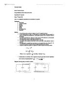
When the switch is in contact with C, the capacitor discharges through the micro ammeter.
This process of charging and discharging occurs times per second. In each second, pulses of charge () flow through the micro ammeter. Hence, the current () through the micro ammeter is given by :
Procedures
1. The circuit was connected as shown in the setup of the diagram. The resistance of the variable resistor was set at its maximum value. The reading of the voltmeter was recorded.
2. The coil of the reed switch is connected to a signal generator. The frequency of the signal generator was adjusted to 400Hz.
3. The signal generator was turned on. The voltage output was increased until a buzzing sound from the reed switch could be heard.
4. The resistance of the variable resistor was decreased slowly until the current shown on the microammeter did not increase any more. The reading of the microammeter was recorded.
5. Steps 3 and 4 were repeated with the other frequencies of the signal generator from 400Hz to 10 Hz. The results were tabulated.
6. A graph of frequency against current was plotted.
The diagram of the setup
Table of data
Data analysis
When the frequency of the vibrating switch is decreased, the current through the micro ammeter also decreases. And the graph shows a straight line passing through origin, which means that the frequency of the vibrating switch is directly proportional to the current passing through the micro ammeter. The charging and discharging processes are complete
Precaution
- Do not set the variable resitor at its lowest value at the beginning of the experiment.
Explanation:The current flowing in the circuit will become the maximum value and it will be large enough to destroy the micro ammeter.
- Avoid adjusting the vibrating switch to a too high frequency.
Explanation:The capacitor may not be fully discharged or charged further.
- A correct scale of ammeter should be choosed.
Explanation:The measured value of current may be out of range of the ammeter if inappropriate ammeter is chose.
The sources of errors in the experiment
- There exists stray capacitors during the experiment which may affect the capacitance of the capacitor.
- The marked value of the capacitance on the capacitor is not the actual value.
- The vibrating switch may not vibrate at the given frequency.
- The value of the current cannot be read accurately as the pointer of the micro ammeter is constantly vibrating with a small amplitude.
Suggest improvement to the experiment
- By using electrostatic or electromagnetic shielding, which prevents a circuit from being exposed to other conductors. Thus, we can reduce the stray capacitance.
- Avoid the existence of any connecting wires near the capacitor.
Limitation of the experiment
- The vibrating switch cannot be set to vibrate at too high feuquency.
Conclusion
The frequency of the vibrating switch is directly proportional to the current passing through the micro ammeter. When the ferquency is set at high value, the value of the current measured is also high. The charging and discharging processes are complete. The marked value of the capacitance on the capacitor is 2.2 , but the value obtained in the experiment is 2.17. There is a discrepency between the two values as erroers existed in the experiment. Errors include the possible stray capacitor, the incorrect value of the capacitance on the capacitor etc.
Discussion
- Why the charging and discharging of the capacitor must be complete?
Ans : If the charging and discharging process are incomplete, there are some charges remain to store in the capacitor, the discharing current measured when it comes to steady value is inaccurate.
- Why we need to set the resistance of the variable resistor its maximum value at first?
Ans : It is because we need to limit the current flow in the circuit to prevent the broken down of micro ammeter due to the extremely large current, and ensure the current not exceed the highest accommondated value.
-
From the graph in step 6, what is the relationship between the frequency of the reed switch and the current flowing in the capacitor?
Ans : . Thus, the frequency of the vibrating switch is directly proportional to the current passing through the micro ammeter.
- Determine the capacitance of the capacitor by using given equation.
Ans :
- Compare the measured capacitance of the capacitor with the value marked on it. Calculate the percentage error.
Ans : The measured capacitance is a little bit smaller than the marked value
- State the sources of error and suggest improvements for this experiment.
Ans : This has been done in the upper part.