Vibratory Analyzer Slot
How would a telegraph operator be able to distinguish different tones reliably? Remember that the operator might have to distinguish eight or more separate messages sent either to separately tuned forks or to a single universal receiver. Both Bell and his competitor, Elisha Gray, confronted this problem after they had established that the transmission of distinct tones was possible. The box labeled "" shows Bell's solution, which he was able to patent. The "P" inside a circle next to the box indicates that the sketch is part of a successful patent and flags patents in our mapping methodology.
The new slot is shown to the right of one of Bell's tuned reed relays. As the steel reed vibrates, it makes contact with a lever, the other end of which dips in and out of two cups of mercury, alternately making and breaking a circuit. (See Figure 4*) Therefore, the harmonic vibrations of the reed were translated into on-off impulses suitable for telegraphy. This lever and twin cups resembled Morse's original telegraph portrule, illustrating the way in which mechanical representations can readily be borrowed from another source.
The Morse device provided Bell with a mechanical representation that he used in his March 6 application. But in his patent, Bell made it clear that it was the principle he was after, not just a specific mechanical representation: "Many forms of circuit breakers for the purpose may be employed such as membranes &c., all that is required being that the circuit breaker shall be capable of vibratory or oscillatory movement, and that its normal rate of movement, when in oscillation or vibration, shall be slower than that of the receiver by which it is actuated." Indeed, Bell later patented an improvement in this vibratory circuit-breaker.
So, by the spring of 1875, Bell had a mental model for a complete system of multiple telegraphy and had succeeded in patenting parts of it. A significant part of this mental model was the idea that the goal in multiple telegraphy was to transmit what Bell called an "undulatory current" as opposed to the intermittent or make-or-break current used in single telegraphy. To trace this important aspect of Bell's mental model, we will have to go to the upper left-hand box of the Master Map.
The Ear Phonautograph
Bell lacked the electrical knowledge and expertise of other multiple telegraph inventors like Edison and Gray. But he did posses a unique area of expertise. He was a teacher of the deaf, and therefore understood the importance of speech in communication. His father, Alexander Melville, had invented a "Visible Speech" alphabet that would help the deaf learn to speak. Bell was similarly interested in devices that would help the deaf "see" speech, as is indicated by the goal box above "The Ear Phonautograph" (see the top left-hand corner of the ).
Bell's interest in teaching the deaf kindled his interest in devices used to visualize sound; these devices are represented on sub-maps beneath the ear phonautograph box. At MIT, he experimented with Koenig's manometric flame and a version Scott's phonautograph that had been improved by Charles Cross' pupil, Charles Morey. Bell planned to use the devices to give a deaf child feedback. Bell would make templates of speech sounds and then instruct the child to speak into one of the devices and reproduce the template pattern. Since Bell could not physically record the manometric flame patterns using photography and since the patterns were difficult to discern, he concentrated on the phonautograph.
Controlled tests of the two devices revealed differences in curves produced in response to the same sound. Bell concluded that the phonautograph device needed extensive modification so that the tracings would match the flame shapes of the manometric capsule. Considering the phonautograph's geometry--with its thin, light membrane and the relatively heavy wooden lever and style moved by the membrane--Bell was struck by the resemblance between the device and the structure of the human ear. The ear analogy suggested the sorts of modifications he might undertake to successfully replicate the flame shapes in the tracings of this device. The modifications aimed to make the analogy between technology and nature more literal. Bell sought to duplicate "the shape of the membrane of the human ear, the shapes of the bones attached to it, the mode of connection between the two, etc."
Bell built an ear phonautograph in 1874 following a suggestion from Clarence Blake (a more detailed picture of this device can be found by clicking on the top level phonautograph box and going to a lower level). It consisted of the bones of an actual human ear, mounted on a wooden frame. When one spoke into it, the bones vibrated; a bristle brush descending from the bones traced the shape of the sound waves on a piece of smoked glass, which could be rolled back and forth underneath..
The box with the wavy line below the phonautograph shows the conclusion Bell drew from this experiment--that sound could be translated into visible waves. From this phonautograph, Bell gained a tactual, "hands-on" understanding of how speech is translated into sinusoidal or undulating waves. From his multiple telegraph experiments, Bell gained a similar understanding of how the vibrations of a reed could be translated intoelect ric current, and reproduced as sound.
The Harp Apparatus
Bell's background in telegraphy and in the visible reproduction of sound come together in the box labeled "Harp Apparatus", which represents a new mental model of how undulating sound waves might be translated into electric currents of the same form. Bell sketched, but never built, this device in the summer of 1874. To understand its function, it is better to refer to its precursor, stored in a sub-map (found by clicking on the top level box). This device consists of two permanent horseshoe magnets with two of Bell's steel reeds on each. Bell hoped such a device would serve as a transceiver for two distinct signals, corresponding to each of the reeds.
Why had Bell decided to substitute a permanent magnet for the electromagnets he had previously preferred in his multiple telegraph experiments? In his own words, Bell realized that:
when a permanent magnet is moved towards the pole of an electromagnet, a current of electricity appeared in the coil of the electro-magnet; and that when the permanent magnet was moved from the electro-magnet, a current of opposite kind was induced in the coils. I had no doubt, therefore, that a permanent magnet, like the reed of one of my receiving instruments, vibrating with the frequency of a musical sound in front of the pole of an electro magnet, should induce in the coils of the latter alternately positive and negative impulses corresponding in frequency to the vibration of the reed, and that these reversed impulses would come at equal distances apart.
In other words, Bell postulates that if a magnet is moving away from a coil half of the time and moving towards the coil the other half then the induced current should imitate the vibrating magnet because the flux will be increasing half of the time (magnet moving towards coil) and decreasing half of the time (moving away). If the flux is increasing and decreasing periodically (at discrete intervals in time) then so will the induced current in the coil.
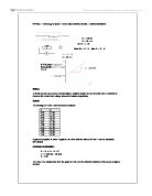
To accomplish this goal, Bell put two steel reeds, A and B on a horseshoe-shaped permanent magnet M. A" and B" represent the same reeds on a duplicate transceiver. When A is plucked, A" will sound, and vice-versa. When A vibrated toward the coil under it, the current became increasingly positive (or negative, depending on which pole of the magnet A was and how the underlying coil was wound); when A vibrated away from the coil, a current of the opposite kind was induced. The signal, therefore, was sent across as a sinusoidal wave, exactly the same form of wave traced by the phonautograph on smoked glass or reflected into a rotating mirror by the manometric flame .
Bell referred to this as an "undulating current", and it became the focus of his successful telephone patent two years later. Bell knew, from Helmholtz, that this wave would "express in a graphical manner the vibratory movement of the air while the reeds were producing their musical tones." Furthermore, the vibrations of the individual reeds on the permanent magnet could be summed into a single undulating curve. Therefore, the device could send A and B as distinct tones and also the sum of A and B. (For a picture of this device, explore the levels below the Harp Apparatus box on the top level box).
Bell realized that if one could combine the sounds from two reeds to make a more complex wave, one could theoretically reproduce any sound by a combination of reeds. This insight is derived from the Helmholtz apparatus, in which multiple tuning forks were used to reproduce vowel sounds.
The result, in Bell's case, was a new mental model for the transmission of musical tones, vowel sounds, or even speech. This model is represented by the harp apparatus, a device Bell sketched, but never built, in the summer of 1874. (For a better picture of this device, explore the levels below its top level box). It essentially involves placing a large number of steel reeds on the poles of a horseshoe-shaped electromagnet long enough to accommodate the reeds. Like the strings of a piano, these reeds would theoretically reproduce any musical tone; like Helmholtz's tuning forks, they could theoretically reproduce vowel sounds as well. For example, when one spoke a vowel into the transmitting harp, a combination of reeds representing the fundamental tone and its overtones would vibrate and this exact combination would be transmitted to the other side, reproducing the vowel sound. This principle had been clearly established by the Helmholtz device which was Bell's original mental model; in this case, however, the single interrupting fork and series of separate resonators were replaced by a series of reeds combining to induce a current in a single electromagnet.
Bell knew he could never build such a device, owing in part to the multiplicity of reeds that would be required, but it served as a new mental model, showing him how the undulating waves traced by the phonautograph could be turned into an undulating electric current and reproduced as sound.
This undulating current was Bell's greatest innovation. Telegraphy involved make or break connections well suited to dots and dashes, but poorly suited to speech. Bell called the current produced by these "intermittent", because it was on or off; when several messages containing dots and dashes were combined, Bell thought the result would be a continuous "on" current, which could not transmit a message. But the result of combining undulating currents would be a sinusoidal curve that would be different for every combination of sounds, therefore allowing one to discriminate among different messages.
Bell believed that a steel reed vibrating over a magnet could never induce an undulating current of sufficient force to transmit over a distance. Therefore, he continued to focus primarily on developing a multiple telegraph, encouraged by his primary backer and future father-in-law Gardiner Hubbard, who urged him constantly to perfect such a device and abandon the pursuit of a speaking telegraph.
The continuation of these efforts is suggested by the "alternate mental model for a multiple telegraph" box. Bell turns to these experiments with rotating magnets just after developing his horseshoe magnet transceiver. The rotating magnets allowed him to induce a current far more powerful than anything he could achieve with a reed vibrating over a permanent magnet.
The June 2nd Experiment
The lines from the Harp and the multiple telegraph come together on the map in a box labeled "Experiment in which one reed relay induces a powerful current in others", which shows two reed relays connected in a circuit. This kind of circuit emerges from Bell's earliest mental model for a multiple telegraph, based on substituting the reeds for Helmholtz's tuning forks. But the harp mental model primes Bell to recognize the significance of a serendipitous discovery he and Watson made on June 2, 1875. Bell had set up three multiple telegraph stations, A, B and C, each with three tuned-reed relays. He wanted to be able to pluck the first reed in A and have the corresponding reeds in B & C vibrate. (For a diagram, explore the levels below the "Experiment in which one reed relay induces a powerful current in others" box). Naturally, these reeds were very difficult to tune and required constant adjustment--shortening or lengthening.
When Bell depressed the telegraph key corresponding to one of the reeds at A, the corresponding reed at B vibrated well, but Watson, who was in another room with C, said it was stuck. To release it, Watson plucked it; Bell noticed that this caused the corresponding reed at B to vibrate powerfully. Bell then listened to each of the reeds at B in succession, placing his ear right against them, and heard both the pitch and the overtones of the tuned reed. "These experiments at once removed the doubt that had been in my mind since the summer of 1874, that magneto-electric currents generated by the vibration of an armature in front of an electro-magnet would be too feeble to produce audible effects that could be practically utilized for the purposes of multiple telegraphy and of speech-transmission."
Here we arrive at one of those moments of creative insight that are often referred to as "mysterious", and, in this case, as heavily dependent on serendipity. Consider Watson's dramatic description:
That undulatory had passed through the connecting wire to the distant receiver which, fortunately, was a mechanism that could transform the current back into an extremely faint echo of the sound of the vibrating spring that had generated it, but what was still more fortunate, the right man had that mechanism at his ear during that fleeting moment, and instantly recognized the transcendent importance of that faint sound thus electrically transmitted. The shout I heard and his excited rush into my room were the result of that recognition. The speaking telephone was born at that moment...All the experimenting that followed that discovery, up to the time the telephone was put into practical use, was largely a matter of working out the details.
Here we have a classic account of the Eureka moment. There is no doubt that this was a very important experiment, but its significance is somewhat exaggerated by Watson: extensive work remained to be done afterwards, and the current insight was grounded in earlier work. Although his early experiments combining two transmitters and receivers in an attempt to build a multiple telegraph were not successful, Bell noticed a particular phenomenon that prepared him to appreciate the serendipitous discovery of June 2nd. When Bell tried to use two of his steel reed relays as transmitters and pressed his ear against one of the receiving reeds, he heard "two musical tones, corresponding in pitch to the two transmitters employed, but different in pitch from the sound produced when the reed of the receiver at [the] ear was plucked with the finger." Bell had, of course, hoped to hear only a single tone corresponding to the pitch of one of the sending reeds; the extra tone was a kind of interference effect that another inventor might have dismissed as noise or error to be removed. Bell knew that this effect depended on dampening the vibrations of the reed, in this case by pressing his ear against it.
So, by June 2nd Bell knew that a single one of his reed relays could receive complex sounds. He also knew that a reed could generate sufficient current to transmit a tone over a distance. What he learned from the serendipitous error involving the stuck reed was that a single reed, when dampened or stuck, could also induce a current sufficient to transmit complex sounds over a distance--at this point, no greater than from one room to another, but the potential for longer transmission was clearly there. The multiple reeds of the harp were not necessary.
Cognitive psychologists have recently begun to study the effect of various kinds of error on scientific reasoning. Typically, the concern in such studies is with how people can be taught to recognize and remove sources of error. But one of the characteristics of genius is recognizing when an apparent "error" is in fact a phenomenon of great significance. Serendipity lies in the beholder. The little mold on one of Alexander Fleming's petri dishes is an oft-cited example. Similarly, Bell confronts an error--a single reed stubbornly produces multiple tones when plucked--and realizes that this apparent problem is in fact an opportunity.
Bell immediately asked Watson to build a working telephone in which a reed relay was attached to a diaphragm or membrane with a speaking cavity over it. As one spoke into the cavity, the membrane would vibrate; these vibrations would be translated into an electrical current by the dampened reed, which would send them to a similar device on the other end. Unfortunately, this device did not produce intelligible speech, though Bell and Watson heard a kind of mumbling that suggested they were on the right track (see the box labeled "Gallows Telephone").
Sound and Electricity as Sinusoidal Waves
Bythe 20th of January,1876, in a patent application, Bell states his mental model of how mechanical motion is translated into electrical current:
Electrical undulations, induced by the vibration of a body capable of inductive action, can be represented graphically, without error, by the same sinusoidal curve which expresses the vibration of the inducing body itself, and the effect of its vibrations upon the air; for, as above stated, the rate of oscillation in the electrical current corresponds to the rate of vibration of the inducing body---that is, to the pitch of the sound produced. The intensity of the current varies with the amplitude of the vibration--that is, with the loudness of the sound; and the polarity of the current corresponds to the direction of the vibrating body--that is, to the condensations and rarefactions of air produced by the vibration.
The "body" he uses to illustrate these vibrations is his standard reed relay mechanical representation. Even though the Gallows telephone does not work, he knows he has discovered the theoretical principle behind a telegraph or telephone. The above passage from his patent application describes a one-to-one correspondence between characteristics of sound and electricity as well as the belief that sound and electricity will form the same sinusoidal curve when transmitted.
The Ear Mental Model
On February 21, 1876, Bell made a statement and a sketch of the mental model that represented the synthesis of the phonautograph and his multiple telegraph experiments. Bell draws an ear with two different mechanical representations next to the bones. On the left is an electromagnet, suggesting that the bones will serve a function similar to the armature on his familiar reed-relay mechanical representation. On the right an iron cylinder is attached to the bones and this vibrates in the center of a magnetized helix with an iron core. Again, Bell had conducted experiments with such an arrangement, verifying that it could produce an undulatory current; he would later develop this mechanical representation into a telephone receiver. Beside the sketch, Bell wrote, "Make transmitting instrument after the model of the human ear. Make armature after the shape of the ossicles. Follow out the analogy of nature."
What Bell first does in this remarkable statement is outline two goals. Cognitive scientists have done extensive work on goals, especially the differentiation between goals and sub-goals.The statement "Make armature after the shape of the ossicles" is a sub-goal under "Make transmitting instrument after the model of the human ear" because the former suggests what needs to be done in a particular slot in order to accomplish the latter. (Note that we use a wedge-shaped box to denote stated, as opposed to inferred, goals).
The statement that he was "following the analogy of nature" illustrates another component of our framework. Inventors and scientists often employ heuristics, or "rules of thumb", to reach their goals. Bell's strategy of "following the analogy of nature" is one such strategy: when in doubt, try to copy nature. Note that heuristics depend heavily on mental models; in order for Bell to copy nature, he has to have both a clear understanding of the ear and a set of mechanical representations that he can employ.
Bell's Gallows telephone followed this mental model--it is a kind of electromechanical ear. If so, why does Bell state his mental model a year later? Actually, it is rare for an inventor or scientist to state their underlying assumptions explicitly. Bell is a theoretical inventor; therefore, he pays careful attention to developing and articulating a mental model. He might have had the rough outlines of this mental model long before the February 22nd date on which he wrote it in his notebook, and merely noted it as both a reminder to himself and in preparation for future patent litigation. Or this entry might have represented a moment in which he synthesized earlier insights into a conscious statement .
By now, the reader may be somewhat bewildered by the variety of uses to which we have put the term mental model. We used it to describe Bell's understanding of the Helmholtz apparatus for reproducing vowel sounds, Bell's own harp apparatus, his understanding of how sound and electricity could be visualized in terms of sinusoidal waves, and finally, this sketch of the bones of the ear next to two different mechanical representations.
Mental model is a 'scruffy" term, which means it cannot (to the dismay of philosophers) be defined precisely. But the term draws our attention to the way Bell imagines devices and how they work. Some of his mental models seem very close to practical devices; others, like the harp and the ear, are flights of the imagination that could never be built. But they allow him to carry out thought experiments, to visualize and manipulate the relationships between sound, electricity and magnetism. Given his limited electromechanical skills, mental modeling is especially important to Bell.
A Slot Diagram Based on a Patent Drawing
Below the mental model on our main map is a slot diagram based on Bell's patent signed on January 20, 1876 and submitted on February 14th . The oval in it connected to this slot diagram reflects the fact that Gardiner Hubbard actually submitted the patent for his son-in-law. Bell was waiting for a possible British patent when Hubbard decided it was time and they could afford to wait no longer. As it turned out, Hubbard's timing was very tight--a few hours later, Elisha Gray submitted a caveat for a speaking telegraph.
The oval, in this case, reflects an important change of heart that we need to explain more fully. Hubbard had gone from being suspicious of Bell's telephonic researches to becoming a backer. Indeed, it was Hubbard who built the corporation that bears Bell's name and made the inventor a millionaire. This oval will eventually include a sub-map that sketches Hubbard's path from telegraph to telephone backer, and records the early details of the agreements that lead to the Bell corporation. The map can serve as a reminder of areas that need work.
Generally speaking, we find that patent drawings make the best basis for slot diagrams, although--given the limited number of patents filed by Bell--we often have to use his notebook sketches. Patent applications provide the best sketches and most articulate description of the goals and sub-goals reached by inventors.
In Bell's case, the "Ear and Membrane" slot indicates that Bell could use a number of different devices to realize the same function as the anatomical parts. The "Ossicles Slot" has the same meaning; the patent diagram shows one of his steel reed armatures serving the function of the bones, but the ear diagram in his notebook makes it clear he considered alternate mechanical representations. Bell's ear mental model suggests nothing about how he is going to accomplish long-distance transmission, so we have introduced a "Line" slot. Note that this slot overlaps with the Ossicles slot; this is deliberate, to indicate the obvious--that improving the relationship between the armature and the induction coil is one of the keys to long-distance transmission. Slots are not necessarily mutually exclusive. We have also noted slots for "power source", to indicate that he could remove the battery or increase its strength, and a "motion into current" slot, to indicate that he could experiment with different ways of translating the motion of the armature into an undulating electric current. Finally, there is a "receiver" slot, to denote the fact that Bell will try a variety of substitutions to improve reception, including devices which do not look exactly like the transmitter. Again, whatever he learns about armatures in the Ossicles slot could be applied to the receiver.
In Bell's case, we could possibly have determined his slots simply from looking at his ear diagrams. But we do not determine slots solely on an a priori basis; instead, we also look closely at the experiments an inventor does,to see what areas he is concentrating on. In other words, we could have divided the ear up very differently, but we have tried to stick hard to Bell's divisions. Slots, then, become an important tool for mapping the invention process.
Bell's patent was eventually granted, and became the focus of endless litigation, but that lies beyond our story. Part of the frustration experienced by other inventors like Edison and Gray comes from the fact that when Bell filed, he had no working telephone. But he did have a mental model, as our slot diagram illustrates. In his subsequent experiments, Bell opened certain of these slots and tried to insert or develop different mechanical representations to improve performance.
The First Transmission of Speech
When Bell obtained his patent, he still did not have a working device. The line of experiments that led to the first successful transmission of speech is depicted in the two boxes below the "Slots in Bell's Ear Mental Model" box (by below, in this case, we mean lower on the same page in Mosaic, connected by arrows). To see a detailed rendition of the actual experiments, one needs to click on these two boxes. The upper box describes experiments with devices that look much like the ear mental model.
The box that is lower and to the right is connected by a minus and a plus sign with devices next to each. This is a short-hand way of indicating that to get from one box to the other, Bell removes an electromagnet and substitutes a dish of water. The box called 'spark arrester" above it is connected by an arrow, to indicate that Bell had previous experience using water as a medium of resistance in a device that prevented sparks in a telegraph rely. The liquid experiments led to the famous "Watson--come here--I want you" result obtained on March 10th. Text describing these experiments in detail can be obtained by clicking on the detailed representations of the experiments themselves.
The upper level map needs to be continued to Bell's second patent, obtained in January of 1877. This second patent includes devices that look much like those in his first patent; he abandoned the liquid transmitter variations, which is why they are depicted off to the side. The story of why he did this is told elsewhere, and will be incorporated in future versions of the map.
Endnotes
-
"We" refers to a team of faculty and students that included my colleague W. Bernard Carlson and several recent graduates of the University of Virginia, including Tamar Lieberman, Matthew M. Mehalik, Christy Nilsen and Charles Twardy.
-
D.A. Hounshell makes the case that Bell deliberately sought to establish strong links to the scientific community of the day, whereas Elisha Gray did not. Bell's careful attention to science and scientists was one of the reasons for his success. See "Bell and Gray: Contrasts in Style, Politics, and Etiquette", IEEE Proceedings 64 (1976) :1305-14; and "Two Paths to the Telephone", Scientific American 244 (January 1981) : 156-63.
-
R. Bruce (1973). Alexander Graham Bell and the Conquest of Solitude. Boston: Little, Brown & Co., p. 51. Bruce cites a source from 1879-- much later than the actual event. This is not a reliable source because a later reconstruction has great potential for distorting the original events. We have not been able to find more reliable sources with earlier dates to describe this event. In an account from 1877 Bell indicates that he understood Helmholtz by describing that the Helmholtz apparatus "produce[s] vowel sounds artificially." (George B. Prescott. (1972) Bell's Electric Speaking Telephone: Its Invention, Construction, Application, Modification and History. New York: Arno Press. pp.66-67) So, we must be careful in interpreting this bit of information, since it does not come to us directly from primary sources written at the time of the event.
What is clear is that Bell saw his early multiple telegraph experiments as similar to Helmholtz's experiments with vowel sounds--"My knowledge of Helmholtz's apparatus for the artificial production of vowel sounds incited me to experiments of a similar character..." (The Bell Telephone: The Deposition of Alexander Graham Bell in the Suit Brought by the United States to Annul the Bell Patents. (1908) Boston: American Bell Telephone Company. p. 12)--whereas, in fact, Bell's and Helmholtz's experiments were quite different.
-
See R. Bruce (1973). Alexander Graham Bell and the Conquest of Solitude. Boston: Little, Brown & Co., pp. 50-51.
- R. D. Tweney (1989) makes a distinction between framework and theory:
Truth claims in a theory are based on the familiar strategies of scientific practice, while truth claims in a framework rely on interpretive procedures more akin to the methods of historical scholarship,. A theory is an attempt to construct a model of the world which meets certain criteria of testability; it makes predictions, is potentially disconfirmable, and has interesting consequences. A framework is an attempt to re-construct a model of the world which meets criteria other than testability as such. An adequate framework is one that is consistent with the details of the process, is interestingly related to our theories of the world, and reduces the apparent complexity of the real world process in a way which permits anchoring the framework to the data. In effect, an adequate framework must allow us to see order amid chaos ("A Framework for the Cognitive Psychology of Science," in B. Gholson, W.R. Shadish, R.A. Niemeyer & A.C. Houts (Eds.) Psychology of Science. Cambridge: Cambridge University Press, p. 344).
Our framework and maps allow us to perceive order among the chaos of the inventor's sketches, artifacts, caveats and notes, Our framework might eventually evolve into a more formal, theoretical model, but at the very least, it provides us with a rigorous basis for comparing inventors.
-
For good reviews, see D. Gentner & A.L. Stevens, Mental Models. (Hillsdale, N.J.: Lawrence Erlbaum Associates, 1983), 99-129 and W.B. Rouse & N.M. Morris, "On Looking Into the Black Box: Prospects and Limits in the Search for Mental Models," Psychological Bulletin, Vol. 100 (1986) : 349-363.
-
This term is borrowed from R.J. Weber & D.N. Perkins (1989) "How to Invent Artifacts and Ideas," New Ideas in Psychology, 7:49-72.
-
A.G. Bell, The Multiple Telegraph Boston: Franklin Press, Rand, Avery & Co., 1876, p. 8. Klahr and Dunbar, in an experimental simulation of scientific reasoning, found that college students adopted either a theoretical or experimental style; Bell obviously leaned more toward the former, which in Klahr and Dunbar's artificial task was more effective. See D. Klahr and K. Dunbar, "Dual Space Search During Scientific Reasoning," Cognitive Science, 1988, Vol. 12, 1-48.
-
J. Baille. The Wonders of Electricity. New York: Charles Scribner, 1872), pp. 140-143.
-
Bell's sucessful patent was number 174,465. Gray's rejected patent application was filed on 29 October 1877.
-
The sketches of transmitter and receiver here are not juxtaposed in this way in the original documents; we have done so to illustrate Bell's alternate mental model. For the rotating magnet, see Bell, The Multiple Telegraph, p. 14. Bell eventually patented the general principle of using rotating magnets to induce a continuous current in a closed circuit; see A. G. Bell, "Generating Electric Currents," U.S. Patent No. 181,553, (filed August 12, 1876, granted August 29, 1876). For the nail in a helix, see letter from A.G. Bell to Gardiner Hubbard on November 27, 1874. Bell Family Papers, Library of Congress, Box 80.
-
Bell to Hubbard, op cit.
-
For more details on Bell's multiple telegraph experiments, see M.E. Gorman, M. Mehalik, W.B. Carlson & M. Oblon, "Alexander Graham Bell, Elisha Gray and the Speaking Telegraph: A Cognitive Comparison", History of Technology, Vol. 15, 1993. For example, in the case of the nail in a helix, Bell was re-discovering a principle used by Philip Reis in the first device labeled a telephone. Bell claims he made the discovery independently, without knowing Reis' work. Those wishing to receive preprints of this paper can write to the senior author of this chapter.
- Bell filed an application for this patent on March 6, 1875. The patent "Improvement in Transmitters and Receivers for Electric Telegraphs" was granted on April 6, 1876 as Patent No. 161,739. The patent shows the circuit-breaker as part of an autograph or facsimile telegraph. Bell attached this mechanical representation to the autograph telegraph, in part, to avoid an interference with Gray; as he said in a letter to his mother and father, March 5th, 1875:
My lawyers were at first doubtful whether the examiners would declare an interference between me and Gray as Gray's apparatus had been there for so long a time.
They feared I had but a poor chance--and my spirits at once fell to zero. They said it would be difficult to convince them I had not copied. When however they saw the "Autograph Telegraph" developed from the multiple telegraph --they at once said that was a good proof of independent invention as Gray had no such idea.
-
Brooke Hindle, Emulation and Invention, New York: W. W. Norton & Co., 198= 1.
-
A. G. Bell, "Improvement in Transmitters and Receivers for Electric Telegraphs," op cit.
-
A. G. Bell, "Telephonic Telegraph Receiver," Patent No. 178,399, filed April 8, 1876, granted June 6, 1876.
-
The Bell Telephone (1908), 23-29.
-
A.G. Bell, "Telephonic Telegraph Receiver," 21.
-
The Bell Telephone (1908), 34. Bell is reporting his understanding at a later date, during patent testimony (date 4 April 1892). Bell claims to have arrived at this understanding in the summer of 1874.
-
Bell felt that the the first "telephone", developed by Philip Reis, in Germany, worked on this make-or-break principle; as a result, it could reproduce the pitch of a vowel, but not the complex overtones represented by the multiple resonators in the Helmholtz apparatus. see The Telephone Appeals. Boston: Alfred Mudge & Son Law Printers, 1887. pp. 104-110.
-
Gardiner Hubbard eventually decided to support his son-in-law's telephonic researches, and ended-up being the principle founder of the Bell Telephone Corporation. It was Hubbard who made Bell a millionaire (see Bruce, 1973).
-
The Bell Telephone (1908), p. 59
-
See D. N. Perkins, The Mind's Best Work Cambridge: Harvard UP, 1981; and M. Boden, The Creative Mind: Myths & Mechanisms. New York: Basic Books, 1990, for a summary of the literature on creativity and insight that includes arguments about how these "mysterious" processes can be unpacked and studied.
-
T.A. Watson (1913) "The Birth and Babyhood of the Telephone" Address delivered to the 3rd Annual Convention of the Telephone Pioneers of America at Chicago. Reprinted by the American Telephone and Telegraph Co., pp 10-11.
-
A.G. Bell, The Bell Telephone, p. 16.
-
Bruce, op cit, p. 147.
-
See chapters 4-6 of M.E. Gormans Simulating Science: Heuristics and Mental Models in Technoscientific Thinking. Bloomington: Indiana University Press, 1992, for a description of this research.
-
G. MacFarlane (1984). Alexander Fleming: The Man and the Myth. Cambridge, MA: Harvard U. Press.
-
A. G. Bell, "Improvement in Telegraphy," Patent No. 174,465, witnessed 20 Jan 1876, submitted 14 Feb 1876, granted 7 March 1876. Reproduced in The Bell Telephone: The Deposition of Alexander Graham Bell in the Suit Brought by the United States to Annul the Bell Patents. Boston: American Bell Telephone Company, 1908, p. 455-56.
-
Experiments Made by Alexander Graham Bell, vol. I, p. 13.
-
Ibid. Exptl Notebook vol. 1, p. 13.
-
See, for example, R. Wilensky, Planning and Understanding: A Computational Approach to Human Reasoning. Reading, MA: Addison-Wesly, 1983.
-
There is a long literature on scientific heuristics in cognitive psychology; see, for example, D. Kulkarni & H.A. Simon, "The Processes of Scientific Discovery: The Strategies of Experimentation", Cognitive Science. Vol.12 (1989) 139-175; and M.E. Gorman & W.B. Carlson , "Can Experiments Be Used to Study Science?" Social Epistemology 3(1989) :89-106.
-
Edison describes his mental model based on Reiss in patent testimony: "My sketches were rough ideas of how to carry out that whch was necessary in my mind, to turn the Reiss transmitter into an articulating transmitter. They were notes for future use in experimentation." (from Edison testimony, "The interferences on Telephones between Thomas A. Edison, A. E. Dolbear, Elisha Gray, A.G. Bell, J.W. McDonough, G.B. Richmond, W.L. Voelkers, J.H. Irwin, and Francis Blake, Jr.," deposition taken November 8, 1880, p. 9 paragraph 26).
-
Indeed, Bell's notebook was started in response to Gardiner Hubbard's reminder that he ought to write everything down.
-
See Bruce, op cit, pp. 165-168.
-
See M.E. Gorman, M. Mehalik, W.B. Carlson & M. Oblon, "Alexander Graham Bell, Elisha Gray and the Speaking Telegraph: A Cognitive Comparison", History of Technology, Vol. 15, 1993, 1-56.