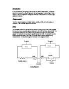
The bulb illuminates once the power supply is switched on. The variable resistor is set to its minimum value so that the bulb shows maximum illumination. The reading on both the voltmeter and the luxmeter are taken. The pointer on the variable resistor is now stepped up by a certain distance. The bulb decreases in illumination and once again, the values on the voltmeter and the luxmeter are taken. The process is repeated until the variable resistor reaches its maximum resistance.
After that, we use our hand to cover the LDR from a certain height and make measurements of the corresponding voltage and lux readings. This height is then gradually decreased while the readings are taken at each decreased height. The process is continued until the LDR is totally covered.
All readings are tabulated in a table as shown below:
Explanation
When bright light falls on the LDR, its resistance falls. Therefore, the current in the circuit increases. A potential difference is generated at the same time. As a result, the reading of the voltmeter across the fixed resistor increases. (Since V = IR i.e. V is proportional to I)
The vice-versa happens when dimmer light or no light at all falls on the LDR.
A luxmeter measures the brightness of light in lux whereas the voltmeter measures the corresponding value of V.
Notes
- A bulb of a very low voltage was used. So a 1.6kΩ fixed resistor was used to avoid accidental blowing up of the bulb.
- The voltage across the D.C. power supply i.e. 5 V was found simply by connecting the voltmeter to the D.C. power supplies and not including any other instruments.
- A measurement of the background illumination was found with the luxmeter while the bulb was switched off. This background illumination is NOT subtracted from the values of my lux readings that follow, since it is not possible to have an illumination-free environment due to sunlight other than a dark room.
Table
READINGS 1
The formula used for finding the mean values wherever necessary was
(READING 1+ READING 2) / 2
For the process of elimination of ‘rogue’ values and hence to achieve more accuracy, I repeated my experiment again and thus took a second set of readings. These are tabulated below.
READINGS 2
Graphs
After tabulating my measurements and calculating the mean values where necessary, I plotted graphs for both readings 1 & 2.These graphs are plotted below, keeping in mind the need for a line of best fit.
Initial Problems and how they were overcome
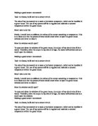
Safety concerns
- Due to safety concerns, D.C. power supplies were used instead of A.C. power supplies.Extra low voltage DC is safer than AC. Anything less than 120 volts DC is not considered lethal, whereas with AC you need to come as low as 32 volts!
- Care should be taken with the eyes. Even though the voltage of the bulb used in the experiment is small, looking at the bulb for a short time even when taking down luxmeter readings can cause eye strains. To reduce this effect, a retort stand with a barrier can be set to obstruct the light from the experimenter’s eyes (but not the LDR or the luxmeter).
All electrical equipments and connections should be handled carefully and only disconnected from the circuits when the power supplies are switched off.
Acknowledgements
The following source was used for a part of this coursework relating to the safety concerns of D.C. over A.C.
A.C.