
Review of Electronics Systems in Society
Electronics Research Assignment Review of Electronics Systems in Society Mobile Phones: Mobile phones are small, portable devices used for voice or data communication using cellular radio networks. In recent years, the technology of mobile phones has advanced much and many additional features have been added such as digital cameras, video recording, internet and email. MP3 Players: These are devices used for storing and playing music. The music is stored digitally as files in formats such as MP3 and WMA. Although the devices are small they can store up to 160 GB of data or around 50,000 songs. People can therefore take their entire music library with them wherever they go. Computers: Machines used to store data and perform complex calculations using sets of instructions called programs. They can be used to carry out many tasks such as word processing, graphics and electronic communication. Television: A system of sending and receiving pictures and sound by means of electronic signals transmitted through wires and optical fibres or by electromagnetic radiation. (MSN Encarta). Television is a source of information and entertainment. Recently television technology has developed and digital television has become more and more used with better picture quality and more channels. General Effects of Electronic Systems in Society Positives * Electronics allow widespread

Building a Sensor to Measure Weight, using a Potential Divider and Wheatstone Bridge.
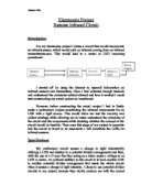
Building a Sensor to Measure Weight, using a Potential Divider and Wheatstone Bridge. Initial Ideas: Firstly I needed to have an idea of what I would have liked to investigate about sensors, whether it be to evaluate against a ready-made sensor or to build and calibrate a sensor. I decided on building and calibrating a sensor as I feel it would be more creative. Then I brainstormed a couple of ideas to build, for example measuring the speed of water by measuring the time it takes the water to fill a cup, so increasing its weight. Another idea was to build an accurate weighing device that works in two directions, the first the conventional way using gravity and the other using a pulley system to measure the upward pulling force. I chose the second idea as I felt the first idea would be to long an experiment as it involves more stages of planning. The first idea is very similar as it also measures weight, but has a different specification. In my primary thinking I realised using a potential divider to measure the weight would be accurate and make it easier to involve equipment we have been shown. The first piece of equipment I thought would be a useful item to use was the strain gauge. These measure the strain on a material, in this case a hacksaw blade. The gauge is on top of the blade and when it is bent down the resistance of the gauge increases, where it is bent up it

An electronics firm wishes to introduce a range of low cost alarms. You have been asked to design and produce a prototype for further development by the firm.
Electronics Folder Problem An electronics firm wishes to introduce a range of low cost alarms. You have been asked to design and produce a prototype for further development by the firm. Possible Projects Brief I have decided to design and make a prototype low cost home burglar alarm. Research into Alarms Analysis of commercial alarms From my research into commercial alarms I have found out the following: * All alarms have more than 1 input. * All alarms sound for a time after they have been triggered. * Most alarms sound for a variable time of between 2 minutes and 20 minutes. * All alarms have a sound output of at least 98dB. * All alarms have either a delay between being switched on and being armed or they can be remotely switched on and off from outside the premises. * The better alarms have a small delay between being triggered and the siren sounding. Task Analysis 1 Task Analysis Detecting Burglars Task Analysis Warning People and making the signal last Task Analysis Getting out of the house and switching the alarm ON Task Analysis Getting into the house without sounding the alarm and switching the alarm OFF Specification My alarm circuit must do the following things: * It must sense burglars entering through the rear door. * It must sense burglars passing down the hallway. * It must sense burglars entering through the front door. * It must
Analysis Courseork
Analysis Section "Bin IT" is a newly established company whose purpose is to specialise in educating its customers in the benefits of recycling. Kate Devon is the Chief administrator of the company and does all of the payroll calculations for the pay slips by hand and not only does it take her a long time to do but she often makes mistakes. She has asked me to help her and create a new system that will make the job easier and eliminate their existing problems. I interviewed Kate Devon, the chief administrator to find out about her job, the problems she's having and the user requirements needed. Amy Smith: What are the problems you, as the payslip writer face with the current system? Kate Devon: Well, to start off with it was an alright job to do, I used a calculator to do my calculations and got through the task quite quickly. But after a while I couldn't keep up and the task started to take longer and because I was restricted to time scales I would start to make mistakes. It was such a daunting task to do that I started getting tired throughout the day. Amy Smith: Would you say you would like a new system that is easier? Kate Devon: Yes, after a long hard day my hand gets tired and people often don't understand my writing, they have complained, but there is nothing I can do, I have tried to explain this to them. I would like to see a new system put in place that is

Elecrtonics - Audio Amplifier
Problem: At the moment my computer uses a pair of small active speakers that do not produce very good sound, also when I want to plug my mp3 player into then I have to unplug them from the back of my computer first which usually consists of a lot of wire untangling and takes a while. Solution: To solve the problem I am going to build an amplifier which will take four separate inputs and be able to switch between them. It will produce good sound quality through external, passive speakers Specification for Amplifier: . It must use an op-amp amplifier 2. It must have four inputs 3. It must have a volume control 4. It must have a bass control 5. It must have a treble control 6. It must be able to switch between inputs 7. It must have stereo speaker outputs 8. It must include a power supply. 9. It must have a maximum size of 300x150x250mm 0. It must be completed by 28th March 2007. 1. It must have a mains power switch. There are various ways in which I can approach this task. I will draw three system block diagrams to show different ways in which I could build my amplifier. Solution 1:- Description:- This is a basic amplifier system. It has four different audio inputs. Two processes, the input selector will select the desired audio input to amplify. The amplifier is a single op amp and the output from this will power the speakers. Solution 2:- Description:-
Electronics Project - Remote Infrared Circuit.
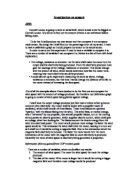
Electronics Project Remote Infrared Circuit Introduction For my electronics project I chose a circuit that would incorporate an infrared sensor, which would pick up infrared coming from an infrared transmitter/source. This would lead to a motor or LED becoming operational. I started off by using the Internet to research information on infrared sensors and transmitters. Once I had collected enough research and understood the principles behind infrared and how it worked I could start constructing my actual project on breadboard. However before constructing the actual project I had to firstly make a preliminary project substituting the infrared components for an LDR with a light source. This would allow me test the circuitry and collect readings while allowing me to better understand the principles of the circuit and the components while deciding whether the concept of the circuit would be feasible. Then once this stage of my project is complete and the circuit is found to be reasonable I will substitute the LDRs for infrared sensors. Specifications My preliminary circuit senses a change in light intensity(By utilizing a LDR and resistor in a potential divider arrangement) and then, with the use of a D type flip-flop acting as a latch, sends a voltage to an LED or motor. An optional addition to the circuit is to have another LDR in another potential divider arrangement
My aim is to produce a line follower robot with a bump sensor which can
Aim: My aim is to produce a line follower robot with a bump sensor which can reverse if it goes off course Research: Line follower robots are most commonly produced to take part in competitions. The purpose of the line follower robot is to follow a line. The robot will only follow a line that is black against a white background or a white line against a black background. This is so that the sensors can distinguish a clear difference in light and so the robot can trace and follow the line. From my research I have decided to use infrared LED emitters (phototransistors). They are fairly cheap but work relatively well. To research into the project I was going to make I looked on the internet to find other examples of the line follower robots. I found many different variations and concentrated on the components used. I looked into books and gathered information on how to assemble the circuit on the breadboard and researched on how the components work. I have researched on the type of amplifiers I could use for the line follower. I will use an amplifier to increase the current as I am using low voltage. I looked on the Maplins website (www.maplins.co.uk) and decided to use the LM386 because it is suitable for low voltage applications and it is relatively cheap. Specification: * The robot has to be able to follow straight lines, curves and turn around corners * It has to

Aim: 'Build a sensor circuit to test the proximity of an object using a light detector to detect light from a bulb reflected f
Aim: 'Build a sensor circuit to test the proximity of an object using a light detector to detect light from a bulb reflected from an object.' In this experiment I am going to build a sensor circuit using an LDR, I will then calibrate the sensor and use my results to test and improve the sensor circuit. The LDR works by having a very high resistance when the light intensity is low, which does not allow current to flow through the potential divider circuit. When the light intensity increases significantly, the resistance reduces dramatically and current can flow through the circuit. The resistor within a circuit can be changed to make the circuit more sensitive. The first thing I had to do was to test two different sensors to see which one had better sensitivity. From my results I could see that the LDR had the biggest input to output difference, meaning it was more sensitive than the photodiode. Next, I had to test which resistance would have the maximum output to input difference and thus give the LDR maximum sensitivity, shown in table A: Resistance/k? V out/V - Light on V out/V - Light off Difference/V 470 7.94 6.39 .55 220 7.93 6.86 .07 00 7.91 6.11 .80 47 7.88 4.94 2.94 22 7.81 3.51 4.30 0 7.66 2.10 5.56 From my results in table A I concluded that the 10k ? setting gave the maximum sensitivity as it had the biggest output to input
Investigation on sensors
Investigation on sensors AIM: Central London is going to have an aerial built, which is said to be the biggest in Central London. My aim is to find out the amount of wind it can withstand before falling down. To do this I shall produce my own sensor and then compare it to a company made sensor. By doing this I shall find out the percentage error of my sensor. I need to have a calibration graph so I could prepare my sensor to the actual sensor. In order to carry out this experiment I need to have a variable to compare it to. There are a number of variables I can compare it to. Below is a list of them with brief explanation: * The voltage, resistance or ammeter: As the wind shall make the motor turn the output shall be electricity being produced. From the electricity produced I can gain the readings of the voltage, resistance or ammeter. This would change with the amount of wind, which would determine how fast the motor turns, meaning how much electricity would be produced. * I could also set up an experiment measuring the same as above, voltage, resistance or ammeter, but this time I would change the distance of the fan to the motor instead of increasing the fans speed. Out of all the examples above I have decided to do the first one and compare the wind speed with the amount of voltage produced. So therefore my Calibration graph is going to consist of wind
Electronics in Society
Electronics in Society Electronics has had a great impact on modern society. Throughout this essay i shall be studying the general development of electronics in modern society. I shall begin by describing some of the different areas of society which have been affected by electronics. Areas of Society that have been Affected by Electronics The home entertainment industry has had a massive impact over the recent years as many new forms of entertainment have been introduced, For example Digital versatile Discs (DVD) and Mini Disks have only recently entered the home. The effects that electronics has had on this industry have been somewhat entirely positive, as without electronics the entire industry would cease to exist. All current media forms are electronic, ranging from the video cassette player, the portable CD player or the home DVD player. These devices have made huge impacts on modern society, as for social aspects more and more people stay in to enjoy these forms of entertainment each year, however this is ultimately leading to a more unfit society and overweight future generations. However the ability to enjoy a cinema-like atmosphere in your own home with technologies such as 'Dolby Surround Sound' widescreen televisions and crystal clear picture quality is highly convenient and enjoyable as a whole. In the manufacturing industry electronics has made a massive