9. Wire strippers and clippers.
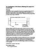
Diagram:
Primary coil Secondary coil Iron core
I will set up the circuit as shown. I will use a power supply and connect it to the coil around the core, using crocodile clips and stripping the insulation from the ends of the core. I will have a voltmeter in parallel to the coil. The coil will be around an iron core. The core is basically an iron rod. There will be the secondary core further up along the rod, which will be attached using crocodile clips to a voltmeter. Using this set-up I can then vary the distance between the coils by using the ruler. The power supply will draw power form the mains. It will be set to AC for the reasons explained beforehand. I will vary the voltage by turning off the power supply and changing it, then turning it back on. I will vary the number of coils by turning the whole thing off and then removing or adding coils to either coil. For voltage I will use a voltage between 0 and 8 volts so as not to have any problems with heat. I will use nominal voltage jumps of 1V but because of the inefficiency of the power box they most probably won’t be 1V. I will have 45 coils in the primary coil and keep that number fixed. But I will change the number of coils in the secondary coil in fixed jumps from 15 to 75.
To keep the test fair I will:
- Keep all variables constant except the one that I am changing.
- Make sure the distance between the coils is 1CM at all times, if it is not being changed.
- Keep the number of turns on the primary core the same.
- I will use the same core throughout the whole experiment.
- Allow the rod to cool if hot.
- I will do repetitions to make sure that the result I have gotten is not a freak result.
I think that this is a good way of doing the experiment because it is fair, and versatile. It is simple so there is less chance of something going wrong, More than one variable is being changed so there is more chance of a pattern emerging. The variables are easy to change.
Safety
- I will make sure the experiment is properly wired and that the wires are not touching, so as not to cause the power box to fuse.
- I will determine a safe level of voltage in the preliminary and not go higher than it.
- I will allow the experiment to cool if it is hot, so nothing has a chance of catching fire.
- I will make sure there is no current going into the core by checking that no connectors are touching the core.
- I will make sure there is no water present near the experiment to prevent an electric shock.
- I will not touch the rod if it is hot (I will use the wire coating condition to see if it is hot)
- I will keep the experiment away from anything flammable so as not to start a fire.
- I will turn off the experiment if the wire coating melts or sparks appear.
- I will make sure to turn off the power supply before changing the voltage so the power supply does not fuse.
- I will turn the experiment off before changing the no of coils or the wire configuration, to prevent electric shock.
I have chosen to vary the no of coils and the voltage in the primary coil. I plan to use a voltage range between 1 and 8 volts, which should give eight results, this ought to be enough to draw a conclusion. Also I want to vary the coil by having 45 turns in the first coil, but use varying turns in the secondary, starting at 15 turns and going up in jumps of 15 turns, to 75. This should give six results, which ought to be enough to determine a pattern. Based on the results of the preliminary, I think that the experiment will be very inefficient, but trends should show up in the results.
Prediction
I think that as voltage in the primary coil increases then the voltage in the secondary coil will increase and the increase will be directly proportionate:
Voltage in
Primary coil
Voltage in secondary coil.
A graph to show the theoretical relationship between voltage in the primary and secondary coils.
This is because the higher the voltage the more energy an electron has, if the electrons have a higher energy then they have stronger fields. A higher voltage in the primary will cause stronger fields in the core, which causes a higher voltage in the secondary coil. And doubling the primary voltage should double the effect, therefore doubling the secondary voltage. I also think that there will be some loss in efficiency meaning that the transformer is about 80% efficient.
100% efficient results should look like this:
A table showing the predicted relationship between voltage in the primary and secondary coils.
Using this we can see that:
So higher voltage input causes higher voltage output.
Also I think that the ratio will have an effect on the secondary voltage:
If both primary and secondary coils are the same in number:
In this case the more coils the more efficient the experiment, the increased coils mean that there is a larger, stronger field induced. These stronger fields are then cut by the increased number of coils, inducing more current, therefore making the whole process more efficient.
If the number of coils in the primary coil is greater than the number in the secondary:
In this case because the electrons in the secondary coil are in less contact with the field lines they therefore receive less energy. However because all the energy ‘must’ go through to the second coil and so the number of electrons (the current) increases. ( Power = current x time) So the voltage and current are inversely proportional. (see graph below) This is called a step down transformer because the voltage decreases.
If the number of coils in the secondary is greater than the number of coils in the primary:
In this because the electrons in the secondary coil are in more contact with the field lines they therefore receive more energy. However because energy is constant the number of electrons (the current) decreases. ( Power = current x time) So the voltage and current are inversely proportional. (see graph below) This is called a step up transformer because the voltage increases despite the fact that the current decreases.
voltage
(v)
Current (a)
A graph to show the relationship between voltage and current.
A table to show the predicted relationship seen when the number of coils on the secondary changes.
This works in that if you double the amount of time an electron influences the magnetic field or the field influences the electron you double the energy resulting in directly proportionate relationship between the number of turns in the secondary coil and the secondary voltage:
No of coils in
secondary
Secondary voltage (v)
Based on this I predict that :
and that:
secondary voltage x no of primary turns = primary voltage x no of secondary turns
Preliminary
I decided to do the preliminary experiment and investigate the variables before I decided what to investigate, as some variables may not have been worth investigating in depth. I used the method and set up described above except there were thirty turns in both coils.
As you can see the voltage is highest when the coils are intertwined together, so the transformer is most efficient then. Based on this I decided to intertwine the coils in order to get the best voltage possible, however, because of time restraints I was easiest to keep the coils 1 cm apart.
The fuse tripped because too much current was drawn. So I decided to use current between 0 and 8.
Obtaining evidence
I had planned to do three repetitions of each experiment but I ended up with the same result anyway, so I decided not to waste time on it. Instead I decided to find the average of the different voltages, and use the averages to see how the ratio of turns affects the secondary voltage.
Analysis
All anomalous results were circled on the graphs. All graphs were checked for direct proportion and if they were it was written in the bottom right corner, and the point, which it became untrue, was also written down. For example in the experiment of 45 coils to 45 coils, this was untrue at 3.4 V. Also if a string of results in a pattern was seen then a curve or line of best fit was drawn for them.
As the results show that primary voltage and secondary voltage are directly, positively proportionate. As one doubles so does the other. E.G in the graph of 45 coils to 45 coils at 1 primary volt the secondary voltage was 0.13V and at 2 primary volts the secondary voltage was 2.6V, showing that if you double the primary voltage you double the secondary voltage.
This is because the higher the voltage the more current, more current causes a stronger field in the core, these then get cut by the secondary coil more, resulting in the electrons induced having more energy (voltage). So higher voltage input causes higher voltage output. This is what I predicted. However the secondary voltage would be about 80% efficient, however it was much lower than this. The average efficiency overall was about 15%, a fraction to what I predicted. This is because much more energy was lost than I expected.
The experiment works well up to a point but then the efficiency decreases and this is because the current limiting switch popped before the full current, and thus full voltage could be achieved. This caused the graph to slope off.
Also the coil ratio and efficiency are inversely proportionate. This is because the higher the ratio the more inefficient the result. This is the opposite to what to I predicted. I think this is caused by the inefficiency of the experiment as a whole. I think that at higher coil ratios the factors that caused a loss of energy were amplified. Meaning that there was more energy lost due to the number of turns etc.
As you can see the efficiency was tiny and the secondary voltage never even came close to the perfect voltage.
The reasons energy was lost were:
-
Resistance in the wire and increasing current. As the voltage increased so did the current to correspond with it. An increased current has more resistance (V/I = R) and coupled with the thin wire, lots of energy was lost to resistance. Most of this energy became heat and the heat was lost to the air and the coil.
-
Eddy currents occurred in the core. A current was induced in the core (because it is made of a conductor) the current had nowhere to go so it swirled in the core, in an ‘eddie’.
-
Flux leakages occurred. This basically means that not all the field lines were cut. This is because the coils didn’t completely cover the core, so field lines were wasted. Also the ends of the core lost a lot of lines. So the energy was lost. A circular or doughnut shaped core would remedy this.
-
Also a humming sound was heard this was because of the iron core. In a magnet all the magnetic domains are in one direction, so the particle field lines are all in the same direction, causing one big field line set. Because an alternating current was used, the magnetic domains had to realign every 50th of a second; this caused them to scrape against each other. The friction caused by this caused heat to build up and caused the core to hum at a frequency of 50Hz (the same frequency of the mains)
-
The coil ratio was not a big a factor as predicted. This was because the coils did not cover the entire magnet so the field lines lost a lot of energy anyway. Also the more the coils the further the current has to move, causing more resistance. So the longer the coil the more energy was lost. This is why the coil ratio and the efficiency were inversely proportional.
Evaluation
The experiment worked quite well despite the low efficiency. It showed the trend and gave sufficient evidence for conclusions. The results were much more accurate than I expected and (excluding the anomalous results at the end) they rarely came off the line of best fit. All the results that did were circled. The method was quite good in theory but in practice fell somewhat, because the efficiency was tiny. The basic method of varying input and checking output is the only way of doing the experiment so it is by default the best. It was fairly good, but with adjustment could be much better. If I were to do the experiment again, I would:
- Use a laminated core to keep the heat from leaking into the core.
- Use a core that is circular, so no energy is lost in the ends of the core by uncut field lines.
- Use thicker wire, so there is less resistance giving more efficiency.
- Use more voltages to get more accurate results.
- Use the coils intertwined instead of 1 cm apart, so as not to have any exposed core.
- Use a pure core, or an alloy of magnetic metals.
- Use more wires
- Use more voltages, in order to get a more accurate mapping of the curve.
- Use a fixed amount of current to get more accurate results
- Check the amount of energy in joules going in and the amount coming out, in order to get a better idea of efficiency.
- Use more numbers of coils
- Use a power box with a dial so exact inputs can be checked
- Have better heat insulation on the wires so energy is not lost
- Have better connections that don’t give as much resistance.
The results were reliable enough for conclusions to be drawn but are not very reliable, even though they correlated well and the trend they show is solid. Because the trend is only visible up to about 3.5V (input) before it starts to fall in efficiency very dramatically. This was because the secondary current never reached it’s full potential, the current limiter always popped because too much current was being drawn. This was because each voltage corresponds to current and if there is resistance then more current is drawn.
Other experiments I would like to do are:
- A repeat of this experiment changing the coil ratios and the input voltages, keeping the number of turns on the primary coil constant. I predict the same result. But I would like to use more voltages, from 0V to 10V.
- Investigating other metals like nickel, steel and copper as cores to see how they affect the experiment, I predict that the larger the atom the stronger the fields.
- The separation of the coils, I predict that the larger the separation the more energy is lost. I want to see how these effect the experiment varying the distance from intertwined, to 10 cm.
- Larger of smaller core. I predict that the larger the core the more efficient the output because of a larger amount of iron atoms, therefore more magnetic fields therefore more field lines, therefore more field lines cut.