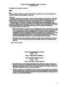
- Yield point. The point, just after the elastic limit, at which a distorting force causes a major change in a material. In a ductile material, like copper, the internal structure changes- bonds between molecular layers break and layers flow over each other. This change is called plastic deformation. (The material becomes plastic). It continues, as the force increases, and the material will eventually break.
Below is a stress/strain graph for a ductile material, like copper.
-
The tension force acts on the wire when it is under stress and strain, it is equal and opposite which, when applied to the ends of an object, such as a wire, increase the length. The intermolecular force resists them.
From my research, I found that the Young’s Modulus of copper is 11.0 x 10¹⁰ Nm-2, from The Usborne Dictionary of Science.
Prediction:
Having overlooked my background knowledge and the research done, I can predict, that Hooke’s law will be true from the start of the experiment to the limit of proportionality shown in fig. 1. Therefore, I feel that the copper wire will follow the same trend line as in fig. 1. I think that when the weights applied, (hence stretching force) is increased the extension increases proportionally. However, this is true up to the point at which the wire reaches its elastic limit.
As well as this, the wires cross-sectional area will decrease as the length of the wire increases because of the tension, stress and the strain, which act on the wire.
Fair test:
However, the accuracy of the experiment depends on the thickness of the wire used initially and the temperature of the wire/ room. The thicker the wire, the more force needed to extend the wire, and vice versa. The temperature affects the state of the wire, if the wire is warm it will extend further, hence the longer length, but a cold wire, will no make much of an extension and is likely to snap quicker than a warm wire. I feel the best way to reach accurate results is to use a vernier scale approach, a laboratory method for measuring the stress and strain in a long, thin copper wire. I have to control the temperature or make sure that the room temperature remains constant. The Young’s Modulus for a particular material is the same, so each diameter of wire should give us the same value for Young’s Modulus.
Apparatus:
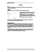
Diagram (fig. 3)
Results table:
The diagram fig. 3 shows the arrangement, which I would use. The advantages in using this method than another is that:
- The scale for measuring extensions is on the reference wire. If the test wire pulls the ceiling downward, the reference wire and the scale move with it. Therefore, the scale measures only the extension, not the sag of the support.
- If temperature changes make the test wire expand or contract, the reference wire changes in the same way.
- A vernier is used to measure the tiny extensions accurately. The vernier is a second scale on the test wire itself, which is accurate to 0.1mm. Dividing the extension by the original length gives the strain.
- You use a micrometer screw gauge to measure the diameter of the thin copper wire. This is accurate to 0.001mm. This gives you the cross-sectional area, and you divide the weight of each load (in N) by the area to get the stress.
I will measure the diameter of the test wire at several places and take an average because the wire may not be uniform, I will measure the extension for loads between 100g and 1100g. I will also check that the length goes back to its original value, this is to check whether the wire has reached the elastic limit of the wire or not.
After having got this data, it could be plotted on a stress/strain graph to find the Young modulus of copper.
Preliminary:
I used four different diameters of wire in this preliminary; I wanted to explore how diameter affects the extension. Doing this will help me decide on which wire to use in the actual experiment. The readings I got were as below:
I feel that the wire of diameter 0.19mm is not suitable for this experiment because of the fact that it does not give me many readings to work with. There are also the matters of safety, the wire snaps suddenly with no warning so it is dangerous to use this wire. The extension in the 0.28mm wire is the most consistent, and I feel that it will give me the readings needed to work out the Young modulus of the copper wire. However, we would not be able to see when the elastic limit is reached because of the limit in the load applied to the wire (1.10kg), unless we find a method of adding more weights. I need to take as many readings of extensions and forces as I possibly can to increase the accuracy of the Young modulus.
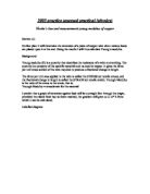
The Young modulus equation is used to find the stiffness of the wire it is defined as below:
We usually plot a graph with stress on the y-axis and strain on the x-axis, the Young modulus is therefore the gradient of the line, it is important to consider the gradient to be on the first straight section of the graph.
The load will be varied, by adding weights and thus the extension shall increase, in the preliminary and research I have found that if we stretched a copper wire to determine its Young modulus, you’d notice that, beyond a certain point, the wire stretched more and more and will not return to its original length when the load is removed. It has become permanently deformed. This is described as plastic deformation. I have discovered from recent class work and coursework, that the diameter of a length of wire, sometimes varies, from one end to the other.
The table below shows the diameter change in a wire labelled as 0.28mm:
As you can see from above, the diameters of the wire, gives me an average of 0.29mm, this in turn will affect the cross-sectional area.
Therefore, having done the preliminary, I think that my predictions lie on the correct lines. It is best to use a thin wire, because a thick wire would not stretch as much for the same force, but I have to consider safety, because the wire snaps and because it is under tension, it whips back and can cause some damage if the student falls in contact with it. Therefore, under these circumstances, it is necessary to wear safety goggles. If we are using a thick wire, you will find that we will be adding a large load. If the wire snaps, the same hazards would take place as mentioned above but, the weight dropping to the floor will cause damage to the toes etc, if the weight falls on the foot, so keep a safe distance as soon as the extra load is added. DO NOT ADD THE WEIGHTS QUICKLY AS THE WIRE IS SENSITIVE WHEN THERE IS ALREADY A LARGE FORCE APPLIED ON IT.
The vernier scale is sensitive, so we have to pay particular attention to how much force we apply, because the maximum extension, which can be read, depends on the size of the scale. Due to the increase in the average cross-sectional area, which affects the extension in the wire, we need to increase the accuracy of the readings by taking repeats, using different wire of the same diameter, and again take measurements of the diameter, with use of the micrometer. This increases the reliability of the results and hence the Young’s modulus of the copper wire.
The vernier scale method is much more accurate than the clamp and pulley method, which could have been used as well, but as we are aiming for accuracy it is best to use the vernier scale method.
The experiment is to be conducted under room temperature, because the temperature of the wire whether cold or hot reduces the accuracy of the results, the wire stretches more under warm conditions because the wire is less stiff than if it was in cold or even room temperature of 23 oC.
I will have to take account of possible errors, such as the zero error in equipment, and other random and systematic errors, which can occur.
I will try to avoid making the parallax errors, (the error which occurs when the eye is not placed directly opposite a scale when a reading is being taken). This can be made on reading off a ruler. The reading errors (the error due to the guess work involved in taking a reading from a scale when reading lies between the scale divisions, and the zero error (the error which occurs when a measuring instrument does not indicate zero when it should), which can be possible on the vernier scale.
If the zero error happens, then I will adjust the instrument to read zero or the inaccurate zero reading should be taken and should be added or subtracted from any other reading taken. Sometimes the metre rules have worn edges and so I will measure from 10cm instead of 0cm.
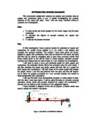
As the wire is stretched, the diameter of the copper wire decreases, we get plastic deformation before it snaps, for example if we look at a copper rod as a large scale to the thin wire you can see from the below that the copper rod ‘necked’ before it broke.
This happens because metals like copper, (above) are ductile- they can have large plastic deformations without fracturing. It happens because atoms move, as the plastic deformation in the crystal structure move, to place of lower stress. The copper becomes thinner when atoms move away from the stressed part. The stress then increases because the cross-sectional area is now decreased. This increases the ductile flow and so the metal yields and gets thinner and thinner. Once plastic deformation starts, atoms will continue to flow without any increase in stress. This stretching under a constant load is called creep. The thinning of a wire/rod is called necking.
There is also the problem that the kg masses may not weigh the given value, there is a small chance that this would be inaccurate, the only way to find out is by weighing the mass using a electronic scale, which is accurate to 0.001g.
Bibliography