“Sybex, Mastering UML with Rational Rose 2002”
2. Requirement modeling- - - - - - - - - - - - - - - - - - - - - - - -
# The Use case diagram #
A use case diagram serves to display the relationships between the actors and the use cases in a system. Use case diagrams are designed to give a rough, informal overview of the possible classes of users and the services and functionalities the system provides to them.
On the Diagram A is described through Use case diagram to the external observer what the system does. The operation of the system is symbolized by the Use Case "Publish unit guide" (oval drawing).
For example:
“The unit leader, publish a unit guide and send them to the Course director and to the student”
[Diagram A]
As we can see on the Diagram A the Unit leader interacts with the system through the use case diagram Publish unit Guide and consequently with the Course director and the student. A use case is a summary of scenarios for a single task or goal. An actor is who or what initiates the events involved in that task. Actors are simply roles that people or objects play.
# The Activity diagram #
Activity diagrams are used to show how different workflows in the system are constructed, how they start and they possibly many decision path can be taken from start to finish. They may also illustrate the where parallel processing may occur in the execution of some activities.
For example Diagram B "Publish a unit guide.", we used the following process for a single decision which depends on another, and on Diagram C is an example of a parallel processing.
The three involved actor of the activity are Unit Leader, Course Director, and Student. The process begins at the black start circle at the top and ends at the concentric white/black stop circles at the bottom. The activities are rounded rectangles.
[Diagram B]
The three involved actor of the activity are Course Director, Second assessor and External verifier. The process begins at the black start circle at the top and ends at the concentric white/black stop circles at the bottom. The activities are rounded rectangles and the parallel processing are forked and joined together with the black straight line.
[Diagram C]
3. Analysis modeling
- - - - - - - - - - - - - - - - - - -
# The Analysis modeling #
Analysis is one of the most important and often most neglected activities of the software development life cycle. Ensures that the systems meets the business needs, can be delivered on time, and have the level of quality and flexibility to easily accommodate future business needs. In software engineering, analysis is the process of converting the user requirements to system specification (system means the software to be developed). System specification, also known as the logic structure, is the developer’s view of the system. Function-oriented analysis: -- concentrating to the decomposition a complex function to simply ones. Object-oriented analysis: -- identifying objects and the relationship between objects. (An object-oriented model of a system consists of a number of objects which are the parts of the system.)
[Diagram D]
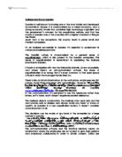
The boundaries/interfaces are:
Lecturer panel, Student panel, Course director panel, Unit leader panel, second assessor panel, and external verifier panel.
Identified relationships/association between the identified objects:
4. Evaluation
- - - - - - - - - - - -
With the Use case, Activity diagram, and analysis modeling the rational rose fully supports all the aspects of a modeling needs. It allows the support of software development of a system modeling with one unified language. Using the Rational Rose application unifies software development teams with a single shared tool.
References
- - - - - - - - - - -
Sybex Mastering UML with Rational Rose 2002
University of Luton. Object Oriented 2003 - Lecture Notes