The technology is already in place to allow the consumers to combine services, such as their credit cards, long distance services, and ATM cards into one card. Smart cards can also perform other functions including providing security for Internet users and allowing travellers to check into hotels. Smart cards provide data portability, security and convenience. Smart cards help businesses evolve and expand their products and services in a changing global market place. Banks, telecommunications companies, software and hardware companies and airlines all have the opportunity to tailor their card products and services to better differentiate their offerings and brands. The combination of applications available on smart cards also may help them to develop closer relationship with their customers. Some of the benefits include: The ability to manage and control expenditures more effectively, fraud reduction, reduced paperwork and elimination of the need to complete redundant, time consuming forms. The potential of having one card with ability to access multiple services, networks and Internet. The benefits of smart cards are endless and they are our future!
3.3. Movement for the Use of Smart Cards in a Linux Environment.
MUSCLE - Movement for the Use of Smart Cards in a Linux Environment.
MUSCLE is a project to coordinate the development of smart cards and applications under Linux. The purpose of this project is to develop a set of compliant drivers, API's, and a resource manager for various smart cards and readers for the GNU environment.
Many years before, magnetic tape stripe card was used for the necessity for every day life. The magnetic stripe works by encoding identification on a magnetic tape similar to how a computer writes information onto a floppy disk. This method is powerful but insure in many instances. These magnetic cards are easy to reproduce and there is no form of encryption.
The Smart Card is different. By using multi directional interaction between the card and the reader true authentication of identity can be met in a more powerful way that is much more secure than the traditional magnetic stripe card. The cardholders’ identity is held on the card via a secret key.
Smart card has a small yet powerful computer built into it. This computer allows the card to interact with the card reader. Some cards such as the Schlumberger Cryptoflex perform cryptographic functions such as key and certificate verification, encryption, random number generation, etc. Others such as the Schlumberger Multiflex cards perform more general functionality. One of the Multiflex cards, the Cyberflex runs Java binaries on the card making it easier to write high-level programs for the smart card. Most smart cards have little program storage on the card, roughly 3 - 8K. The 100 mm. CPU contained on a smart card has roughly the same capability as the 1970's Radio Shack TRS-80 Model 1 Personal Computer. Although the TRS-80 did not run Java binaries or have built in cryptographic functionality, it did operate at roughly the same speed as many modern smart cards.
3.4. Smart Card Technology for 2000 and beyond
Microelectronic solutions for multi-application secure smart cards.
MASSC (Multi-Application Secure Smart Card) focuses on the microelectronics part of target applications, including the development of VLSI semiconductor hardware, embedded software and development methodologies.
Running under MEDEA (Microelectronic Development for European Applications), the Eureka program or pre-competitive collaborative research and development, MASSC brings together SGS-Thomson Microelectronics, Bull CP8, De La Rue Card Systems, Dyade and OscarD. The partners' areas of expertise cover the full spectrum of components and system levels required to meet the emerging needs of the smart card market through the development of highly secure and open platforms.
The aim of the project is to develop new platforms that will offer:
- Advanced VLSI, sub micron chips for embedding in plastic cards;
- High levels of security against a broad range of threats, including fraud, accidental errors and failure through degradation;
- Easy programmability and application downloading capability;
- New and innovative methodologies for fast development of derivatives with security certification;
An open and secure platform:
- MASSC will develop an open and secure platform for dynamic downloading of applications to be executed on an embedded virtual machine. Security kernel and a library of encapsulated functions will be included in the platform to offer built-in security at all levels. The platform will be compliant with industry standards including ISO, EMV, and Java Card;
- The chips will be used highly advanced silicon processing with process technologies of 0.35 down to 0.25 microns. The core CPU will be a 32 bit processor based on SGS-THOMSON's leading edge ST20 RISC architecture;
- Highly secure and open on-chip embedded software will be developed and it will manage the chip resources at both functional and physical levels, performing cryptographic operations, interpreting high-level code, managing firewall and inter-application security protection mechanisms and bootstrapping the software downloading process;
3.5 Prepaid Smart Card Techniques
A prepaid smart card is a kind of technology that can contains stored value, which the person holding it can spend at retailers. A system provider is used to let the retailers to reimburse the actual money after they accept the stored value from card. A system provider receives money in advance from people and stores corresponding value onto their cards. During each of these three kinds of transactions, secured data representing value is exchanged for actual money or for goods and services.
Card Types
- Memory cards – The chip on this card consists only store and a little hardware that prevent the stores data being used by other unauthorized people unless there are password or pins are input correctly.
- Shared-key cards – This card allows communication with any device that have the same keys. The chips are standard micro controller card chips, with masked-in software for the cryptographic authentication algorithms.
- Signature-transporting cards – In this card, it store stores publicly verifiable digital signatures created by the system provider and fills them in like blank checks when spending them.
- Signature-creating cards – These chips also contain a micro controller, but in combination with a dedicated co-processor capable of making digital signatures. Instead of spending signatures created by the system provider, they create their own.
The memory card is suitable for closed systems where there is little incentive for fraud by persons or retailers. The card cost is low but low security makes it unsuitable for more general use. The signature-creating card offer little fundamental advantage over less expensive cards and it is far too slow in signing for highway speed road-tolls and even some telephones.
Shared-key and signature-transporting which is used widely today have same kinds of micro controller chips, and have the same card cost. The system cost with shared-keys is higher than with signature transporting. The main reason is that shared-keys require tamper-resistant modules at all points of payment and processing sites, while these modules are not needed with signature- transporting.
3.6. Conclusions
In this technology world, smart card becomes one of the important technologies in our daily life. Smart card is now one of the advance technology created. Smart card is just a card with a small chip that is stick to it. Smart cards provide data portability, security and convenience. Smart card is very unique and it can be used as personal data storage, where all personal information can be store in the smart card. This technology allows company like banks to create ATM card to user which all information is store in the smart card. Some of the smart card benefits are it has the ability to manage and control expenditures more effectively, fraud reduction, reduced paperwork and elimination of the need to complete redundant, time consuming forms.
Now with Java Card technology, it has the ability to create smart card that can be run only platform. Java Card specifications enable JavaTM technology to run on smart cards and other devices with limited memory. With this two new technology, smart will be more efficient and it will be easily implemented into other applications as well.
In the olden days, magnetic tape stripe card was used for storing data. Its method is powerful but it is easy to duplicate and there is no form of encryption to the data. So everyone may use the data. Now with smart card, the smart card used multi directional interaction between the card and the reader. The data is much more secured and smart card is implemented with encryption algorithms to encrypt the data. Only with password or pins will be able to decrypt the data.
Now smart comes with various type of smart card. One type of the smart card that mentions in the literature review is the prepaid smart card. This kind of smart card stores value into the smart card. Amount of money will be deducted from the value in the smart card. With this kind of technology, we will be able to make payment using a smart card. We don’t have to make any large amount of money where a smart card can pay for everything. Various smart card technologies can make our life easier by storing data in it, but without a good security, then smart card is no different than a piece of worthless card. A good encryption has to be implemented into the smart card for security. Without that, other unauthorized people will easily see the data in the smart card.
Chapter 4: Access Control
4.1 Overview Study Of Access Control Lists
Access Control List (ACL) filters network traffic by controlling whether routed packets are forwarded or blocked at the router's interfaces. The router will examine each packet to determine whether to forward or drop the packet, based on the criteria that has been specified within the access control lists.
Access control list’s criteria could be the source address of the traffic, the destination address of the traffic, the upper-layer protocol, or other information. It is important to note that sophisticated users can sometimes successfully evade or fool basic access lists because that is no any authentication is required. This is the major drawback that needs to be considered.
There are many reasons to configure access lists. For example, we can use access lists to restrict contents of routing updates, or to provide traffic flow control. But one of the most important reasons to configure access lists is to provide security for the network, that is the reason that needs to be focused on.
We should use access lists to provide a basic level of security for accessing our network. If we do not configure access lists on our router, all packets passing through the router could be allowed onto all parts of our network. For example, access lists can allow one host to access a part of our network, and prevent another host from accessing the same area. As refer to the figure below, host A is allowed to access the Human Resources network and host B is prevented from accessing the Human Resources network.
Access lists should be used in "firewall" routers, which are often positioned between the internal network and an external network, such as the Internet. We may also use access lists on a router positioned between two parts of the network, to control traffic entering or exiting a specific part of the internal network.
In order to provide the security benefits of access lists, we should at a minimum configure access lists on border routers. Routers are situated at the edges of the network. This provides a basic buffer from the outside network, or from a less controlled area of our own network into a more sensitive area of our network.
On these routers, we should configure access lists for each network protocol configured on the router interfaces. We can configure access lists so that inbound traffic or outbound traffic or both are filtered on an interface.
Access lists must be defined on a per-protocol basis. In other words, we should define access lists for every protocol enabled on an interface if we want to control traffic flow for that protocol. (Note: Some protocols refer to access control lists as “filters”.)
Lock-and-Key Access Control
Lock-and-key is a traffic filtering security feature that dynamically filters IP protocol traffic. Lock-and-key is configured using IP dynamic extended access lists. Lock-and-key can be used in conjunction with other standard access lists and static extended access lists.
When lock-and-key is configured, designated users whose IP traffic is normally blocked at a router can gain temporary access through the router. When triggered, lock-and-key reconfigures the interface's existing IP access list to permit designated users to reach their designated host(s). Afterwards, lock-and-key reconfigures the interface back to its original state.
For a user to gain access to a host through a router with lock-and-key configured, the user must first Telnet to the router. When a user initiates a standard Telnet session to the router, lock-and-key automatically attempts to authenticate the user. If the user is authenticated, they will then gain temporary access through the router and are able to reach their destination host.
Two examples of when we might use lock-and-key are as follows:
- When we want a specific remote user (or group of remote users) to be able to access a host within our network, connecting from their remote host(s) via the Internet. Lock-and-key authenticates the user, and then permits limited access through our firewall router for the individual's host or subnet, for a finite period of time.
- When we want a subset of hosts on a local network to access a host on a remote network protected by a firewall. With lock-and-key, we could enable access to the remote host only for the desired set of local user's hosts. Lock-and-key requires the users to authenticate through a TACACS+ server, or other security server, before allowing their hosts to access the remote hosts.
The following process describes the lock-and-key access operation:
- A user opens a Telnet session to a border (firewall) router configured for lock-and-key. The user connects via the virtual terminal port on the router.
- The Cisco IOS software receives the Telnet packet, opens a Telnet session, prompts for a password, and performs a user authentication process. The user must pass authentication before access through the router is allowed. The authentication process can be done by the router or by a central access security server such as a TACACS+ or RADIUS server.
- When the user passes authentication, they are logged out of the Telnet session, and the software creates a temporary entry in the dynamic access list. (Per your configuration, this temporary entry can limit the range of networks to which the user is given temporary access.)
- The user exchanges data through the firewall.
- The software deletes the temporary access list entry when a configured timeout is reached, or when the system administrator manually clears it. The configured timeout can either be an idle timeout or an absolute timeout.
4.3 Mosaic 2.0 User Authentications
Mosaic 2.0 allows access restriction based on several criteria:
- Username/password-level access authorization.
- Rejection or acceptance of connections based on Internet address of client.
There are two levels at which authentication information can be passed to the server. The first one will be “global access configuration file” and the “per-directory configuration files”. Global access configuration file is not as common as per-directory configuration files.
Per-directory configuration means that users with write access to part of the file system that is being served (the Document Tree) can control access to their files as they wish. They need not have root access on the system or write access to the server's primary configuration files. Also, the per-directory configuration files are read and parsed by the server on each access, allowing run-time re-configuration. The global configuration files are only parsed on start-up or restart, which usually requires root authority. There is a speed penalty associated with using the per-directory configuration files, but that's the trade-off you have to take. Access control for a given directory is controlled by a specific file in the directory with a filename as specified by the “AccessFileName” directive. The default filename is “htaccess”.
In Basic Authentication (lower authentication method) operation, the password is passed over the network, it is not encrypted but not as plain text, it is "uuencoded." Anyone watching packet traffic on the network will not see the password in the clear, but the password will be easily decoded by anyone who happens to catch the right network packet. So basically this method of authentication is roughly as safe as telnet-style username and password security -- if we trust our machine to be on the Internet, open to attempts to telnet in by anyone who wants to try, then we have no reason not to trust this method also.
In MD5 Message Digest Authentication (higher authentication method), the password is not passed over the network at all. Instead, a series of numbers is generated based on the password and other information about the request, and these numbers are then hashed using MD5. The resulting "digest" is then sent over the network, and it is combined with other items on the server to test against the saved digest on the server. This method is more secure over the network, but it has a penalty. The comparison digest on the server must be stored in a fashion that it is retrievable. It stores the password using the one way “crypt() function”. When the password comes across, the server uudecoded it and then crypts it to check against the stored value. There is no way to get the password from the crypted value. In MD5, we need the information that is stored, so we can't use a one way hashing function to store it. This means that MD5 requires more rigorous security on the server machine. It is possible, but non-trivial, to implement this type of security under the network security model.
4.4 Configuration Of Access Control Lists
Each protocol has its own set of specific tasks and rules required for us to provide traffic filtering, in general most protocols require at least two basic steps to be accomplished. The first step is to create an access list definition, and the second step is to apply the access list to an interface.
For the first step, we create access lists for each protocol that we wish to filter, per router interface. For some protocols, we create one access list to filter inbound traffic, and one access list to filter outbound traffic. To create an access list, we need to specify the protocol to filter, we assign a unique name or number to the access list, and we define packet-filtering criteria. A single access list can have multiple filtering criteria statements.
When configuring access lists on a router, we must identify each access list uniquely within a protocol, by assigning either a name or a number to the protocol's access list. When creating an access list, we define criteria that are applied to each packet that is processed by the router; the router decides whether to forward or block each packet based on whether or not the packet matches the criteria. Typical criteria we define in access lists are packet source addresses, packet destination addresses, or upper-layer protocol of the packet. However, each protocol has its own specific set of criteria that can be defined.
For a single access list, we can define multiple criteria in multiple, separate access list statements. Each of these statements should reference the same identifying name or number, to tie the statements to the same access list. We can have as many criteria statements as we want, limited only by the available memory. Of course, the more statements we have, the more difficult it will be to comprehend and manage our access lists.
For the second step, in some protocols, we can apply up to two access lists to an interface: one inbound access list and one outbound access list. With other protocols, we apply only one access list, which checks both inbound, and outbound packets. If the access list is inbound, when the router receives a packet, the Cisco IOS software checks the access list's criteria statements for a match. If the packet is permitted, the software continues to process the packet. If the packet is denied, the software discards the packet. If the access list is outbound, after receiving and routing a packet to the outbound interface, the software checks the access list's criteria statements for a match. If the packet is permitted, the software transmits the packet. If the packet is denied, the software discards the packet.
- Log File
Most of the client-server applications are using the log file mechanism to keep track on what the user has accessed. Log file format can be classified into two categories, namely, common log file format and extended log file format. Even though the majority of the analysis tools support the common log file format, but the information about each server transaction is fixed. In many cases, it is desirable to record more information. Sites sensitive to personal data issues may wish to omit the recording of certain data. In addition, ambiguities may arise in analyzing the log file format since field separator characters may in some cases occur within fields. Thus, the extended log file format is designed to meet the following needs:
- Permit control over the data recorded.
- Support needs of proxies, clients and servers in a common format
- Provide robust handling of character escaping issues
- Allow exchange of demographic data.
- Allow summary data to be expressed.
As describe above, the log file format permits customized log files to be recorded in a format readable by the generic analysis tools. A header specifying the data types recorded is written out at the start of each log. Log file generators should follow the line termination convention for the platform on which they are executed. Each line may contain either a directive or an entry.
Entries consist of a sequence of fields relating to a single HTTP transaction. Fields are separated by white space; the use of tab characters for this purpose is encouraged. If a field is unused in a particular entry dash "-" marks the omitted field. The meanings of the fields are defined by a proceeding #Fields directive. If a field is omitted for a particular entry a single dash "-" is substituted. Directives record information about the logging process itself. For example:
“Fields: [<specifier>...]” - Specifies the fields recorded in the log.
{Note: The directives Version and Fields are required and should precede all entries in the log. The Fields directive specifies the data recorded in the fields of each entry.}
Analysis tools may generate log summaries. A log summary entry begins with a count specifying the number of times a particular even occurred. For example a site may be interested in a count of the number of requests for a particular URI with a given referer: field but not be interested in recording information about individual requests such as the IP address.
Log file parsers should be tolerant of errors. If an entry contains corrupt data or is terminated unexpectedly, the parser should resynchronize using the end of line marker and continue to parse the following entries. Entries must not contain any ASCII control characters.
- Conclusions
In the network environment, the use of access control is recommended because it may offer a lot of advantages in terms of security, protection and etc. There are several benefits of access controls. First, it can record the details of the user access to the networks. The information is essential in recording the user usage of the computer. Second, when a certain computer has only one authorized user, the package can use the passwords and encryption methods to ensure that only the authorized user has access to the data and programs held on the machine. However, if more than one person is using the machine, the access control package segregates programs and data so that a user may only see and use the files that the package wishes him or her to view.
The implementation of access control in the network environment is very important so that the goals of protection could be achieved. The goals of protection are:
- Prevent mischievous, intentional violation of an access restriction by a user.
- Ensure that each program component active in a system uses system resources consistently with the stated policies for the uses of these resources.
Enforcement of the policies governing resources use. There are varieties of ways involved when policy is concerned. These depend on the hardware being setup and the operating system handled them.
Lock-and-key provides the same benefits as access control lists. However, lock-and-key also has the following security benefits over access control lists.
- Lock-and-key uses a challenge mechanism to authenticate individual users.
- Lock-and-key provides simpler management in large Internet works.
- In many cases, lock-and-key reduces the amount of router processing required for access lists.
- Lock-and-key reduces the opportunity for network break-ins by network hackers.
With lock-and-key, we can specify which users are permitted access to which source/destination hosts. These users must pass a user authentication process before they are permitted access to their designated host(s). Lock-and-key creates dynamic user access through a firewall, without compromising other configured security restrictions.
However, it also has some risks when the lock-and-key method is used. When lock-and-key is triggered, it creates a dynamic opening in the firewall by temporarily reconfiguring an interface to allow user access. While this opening exists, another host might spoof the authenticated user's address to gain access behind the firewall. Lock-and-key does not cause the address spoofing problem; the problem is only identified here as a concern to the user. Spoofing is a problem inherent to all access lists, and lock-and-key does not specifically address this problem.
Access control lists are normally searched sequentially to find a matching rule, and ACLs are ordered specifically to take this factor into account. Because of the increasing needs and requirements for security filtering and packet classification, ACLs can expand to the point that searching the ACL adds a significant amount of time and memory when packets are being forwarded. Moreover, the time taken by the router to search the list is not always consistent, adding a variable latency to the packet forwarding. A high CPU load is necessary for searching an ACL with several entries.
Chapter 5: Proposed Programming Tools and Techniques
- Background Study of Java Programming Tools
Java was created by a team of programmers at Sun Microsystems in 1991. The main challenges of their job were to create a computer language that could be used to build programs that would run in fundamentally different execution platform ands environments. Because these machines provide a wide variety of hardware and software environments, it was necessary that Java be Platform-independent. This would allow the same software to execute without change on a heterogeneous set of devices.
However, java did not become a success. Instead, it was a explosive growth of the World Wide Web and the Internet that caused the Java to receive so much attention. What the Internet has in the common with consumer electronic devices is its diversity of hardware. The Internet allows many different types of computers to be connected together, including the computers that use fundamentally difference CPUs and operating system. Therefore, the ability to write a portable program is as beneficial to the Internet as it is to consumer electronic devices.
There are two types of programs that can be built in Java, which are applications and applets. The feature that is best known about Java is java applet; it can be used to create programs that execute from World Wide Web pages. Java programs made such a big splash on the Web because they offered interactivity in a medium that was largely one way. The Web distributes almost all information in a passive manner. Someone using a browser asks for a page, looks it over, asks for another, looks it over, and so on.
A Java applet running on a Web page provides a much richer experience in terms of information and user interaction. Information can change in response to user input or be updated dynamically as a Web page is viewed. Although Web-based programs are strength of the language, Java is a general-purpose language that can be used to develop all kinds of programs, it include designing application for any computer.
Besides that, a Java program is also created as a text file with the file extension .java. It is compiled into one or more files of bytecodes with the extension.class. Bytecodes are sets of instructions similar to the machine code instructions created when a computer program is compiled. The difference is that machine code must run on the computer system it was compiled for, and bytecodes can run on any computer system equipped to handle Java programs
5.2 Java Tools
In order to write Java applications or applets, it needed more than a language so that it could let the programmer to write, test, and debug the programs. Below are some examples of Java Tools
Compiler
There is a Java compiler called as javac. The Java compiler takes input source code files and converts them into compiled byte code files. These files typically have the extension.java
Interpreter
The Java interpreter, known eponymously as java, can be used to execute Java applications. The interpreter translates byte codes directly into program actions.
Debugger
The Java debugger, jdb, enables the programmer to debug the Java classes. Unfortunately, the Java debugger is a throwback to the pre-GUI debugger dark ages of programming. However, it can use the jdb to set breakpoints, inspect objects and variables, and monitor threads.
Disassembler
The Java Developer's Kit includes a disassembler, javap that can be used to display the public interface, both methods and variables, of a class. Additionally, the Java disassembler includes options to display private members or to display the actual byte codes for the class's methods. This last option can be particularly useful if the programmer want to achieve a greater understanding of the byte codes used by the Java interpreter.
5.2.5 Header File Generator
Because Java is a new language and must fit in a world dominated by C and C++, included in Java is the capability to use native C code within a Java class. One of the steps in doing this is using the Java header file generator, javah.
5.2.6 Javadoc
The programmers fought that it in every way possible. Unfortunately, there is no longer any excuse for not documenting the source code. Using the JavaDoc utility provided with the Java Developers Kit, programmers can easily generate documentation in the form of HTML files. To do this, programmers embed special comments and tags in the source code and then process their code through JavaDoc.
5.2.7 Applet Viewer
This small program provides a real Java environment for testing applets. It loads the HTML file in which the applet has been embedded and displays the application in a browser-like window.
5.3 Advantages of Java
- Secure
Java’s run-time system will perform checks to make sure that programs transmitted over a network have not been tampered with. The code produced by the Java compiler is checked for validity and the program is prevented from performing unauthorized actions.
- Robust
No pointers operations are made available to the programmers. There are no pointer variables, arrays cannot be manipulated through pointers and the integers cannot be converted into pointers. There is no chance of a program corrupting memory through a dangling pointer.
- Multithreaded
Java has built-in support for multi-tasking. A java program may create any number of threads, which appear to execute in parallel.
- Dynamic
Java is designed to accommodate the fast-paced, modern worlds of software development in which components of a system may change on a regular basis. Java’s run-time linking guarantees that a program always loads the most recent version of its library modules. It also reduces recompilation by making it possible to add methods and instance variables to a library without having to recompile its clients.
- Portable
Java achieves its portability by completely defining all aspects and properties of all types, leaving no decisions to the compiler writer. Java’s libraries are designed for complete portability.
- High-Performance
In Java, greater speed could be achieved by translating Java’s byte codes into native machine instructions. After this native compilation, the performance of Java is almost same as C or C++.
.
- Disadvantages of Java
- Immature
Although the Java language itself is unlikely to change dramatically, people can expect significant changes in the Java API and associated technology. Although Java grows very fast, it is still young if we have a look at C or C++.
- No Guarantee Probability
Although Java has the advantages of portability, it does not mean that it can run in all the platforms. This is due to the lack of upgrading of hardware and software in the old systems.
- Speed Issues
The speed of Java application is not fast enough if it has not yet been converted into native code. With ever-faster computers available at bargain prices, Java should be fast enough for all, but the most-intensive programs.
5.5 Forte of Java
Forte for Java is the only development tool needed for building Java applications on any platform. It is fully modular and easily extensible because it is completely open and based on the NetBeans[tm] Tools Platform. The Forte for Java IDE enables us easily and quickly creates Internet services and solutions with 100% Pure Java[tm] code on the Windows, Linux, or Solaris[tm] Operating Environments.
This powerful IDE simplifies the tasks we perform most often: compiling, building, browsing, editing, and debugging. Its outstanding GUI builder and JavaBean[tm] assembly tools make it easy to get and stay productive, and it even includes a JPDA-compatible debugger for distributed services and applications. Depending on our development needs, we can choose from two editions of the Forte for Java product:
-
The Community Edition product is offered at no charge and includes a complete and highly integrated set of tools, including a Web browser and a Web server. With this edition, any developer can build stand-alone applications, applets, JavaBeans, and Java clients.
- The Internet Edition product includes all the functionality in the Community Edition plus support for teams of developers building database-aware Web applications. This edition includes integration with Tomcat (a Java Server Pages 1.1/Servlets 2.2 reference implementation), and it expands on the functionalities of the Web browser and Web server in the Community Edition. Its plug-in components are ideal for speeding our dynamic Web content development.
Forte for Java includes Form Editor, multi-threaded debugger, explorer and properties window, object browser, source synchronization, update center and etc. The Form Editor includes advanced support for Java layout managers, including the “GridBag layout customizer”, which makes the most complex standard Java layout manager easier to use. Besides that, the Form Editor also enables us to use any JavaBeans component for visual development since the Form Editor is using the standard Abstract Window Toolkit (AWT) and Java Foundation Classes (JFC) components.
Forte for Java provides full support for multi-threaded debugging and standard debugging features such as breakpoints, watches, trace into, trace over, and trace out. With the use of the object browser in the Forte of Java, all the source codes are logically presented in one streamlined view. We can view our applications by package, object, and member (or bean patterns), as well as apply filters to customize what is displayed.
Forte for Java also provides CVS (Concurrent Version System) support, Javadoc support, special supports for JavaBeans components and etc. The Java source synchronization feature can save the user time by automatically generating all of the implementation methods used for the source code.
Forte for Java provides special support for creating JavaBeans components, including generation of properties, event sets, and bean info. The user can also customize them and add them to the IDE so that they can be easily dropped into applications.
Forte for Java provides us an easy access to Java API documents from within the IDE. We can also have Javadoc comments automatically generated for our files and produce our own Javadoc documentation.
5.6 Conclusion
As a conclusion, Java has significant advantages, not only as a commercial language, but also as a teaching language. Java allows learning object-oriented programming without exposing them to the complexity of C++. It also provides the kind of rigorous compile-time error checking. It also allows introducing GUI programming, networking, threads and other important concepts used in modern-day software.
After conduct the thorough research on the Java programming tool, the team examined that the Java programming language is very complex as compared to other programming languages such as Visual Basic. However, Java programming is very flexible and each of the classes can be reuse in different system. In creating the user interface, the team found that it is not as easy as Visual Basic. The team is required to spend a lot of time and efforts in designing the user interfaces.
Chapter 6: Requirements Specification and Feasibility Study
- Requirements Specification Document
In current laboratory, it has all together 393 computers and spreads in 11 laboratories. There are about 15 laboratory staffs maintaining these laboratories. The management is planned to put the current laboratory system into a client-server environment.
The new proposed system should be able to perform the following:
- A distributed network system based on client-server concept. It is hoped that there will be at least one server to centralize all the monitoring of 393 computers.
- The database on the server will be updated instantaneously.
- The server will wait if there is any request from the client to read from the database.
The proposed system is mainly consists of three different kinds of user, namely, students, staffs and supervisor. All these levels of user will have their own roles and responsibilities towards the proposed system. If there is a free lab, the Lab Assistants is only responsible to see the student ID and secure physical lab facilities.
When the student comes in, they are required to present their student ID to the Lab Assistant (staffs). Once the Lab Assistant has approved them to use the computer, they can choose any available PC and login the computer. If there is a free lab, the Lab Assistants is only responsible to see the student ID and secure physical lab facilities
For the login process, students or staffs are required to use the valid smart card and also provide their registered username and password. The system will verify the students’ or staffs’ username and password based on the information provided in the Lab User Master Record. For the incorrect username and/or password, the system will reject them. In this case, they are required to re-login the system.
Once the students or staffs have login into the system, the system will log the computer by creating the log file. At that moment, the login information such as login date, login time, host name and etc will be recorded. All the log files will be sent to the server and furthermore store the logging information in the Lab Access Master file. If there is any student or staff who wants to change their PC, they should logout the previous computer before they could login into the other computer.
For the new smart card applicants, their requisition should be approved before the new smart card could be produced. During the application process, they should provide their registration ID. For the valid registration ID, the new smart card requisition will be approved. All the user information will be stored in the Lab User Master Record if the smart card requisition has been approved. For the redundant username, the system will acquire the new smart card applicants to provide another username. Once the smart card requisition has been approved, new smart card will be produced.
By the end of every month, the system will retrieve the Monthly Lab Access Logging Information from the Lab Access Master file, produce the Monthly Lab Access Review Report and sends it to the Lab Administrator. Besides that, Lab Administrator will also be able to retrieve all the information from the server.
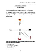
6.2 Hardware and Software Requirement
- Hardware
- Networked server computer and client computers
- Memory should be more than 128 Mbytes;
- CPU should be Pentium III 600 MHz or faster;
- Hard disk should be more than 10.2 Gbytes.
- Super VGA display card
- 15” color monitor;
- 100/10-auto adaptec network card with RJ-45 connector;
- Five-category network cable with RG-45 connector.
- The 8-end 100/10-auto adapter hub.
- Floppy disk driver;
- Standard 102 keys keyboard;
- Standard MS mouse.
* The hardware above can be an optional item.
- Software
- Windows 98 SE/Windows Millennium Edition
-
JavaTM 2 SDK, Standard Edition Win32 Version 1.3
- Java Beans Development Kit (BDK) 1.1
- Microsoft Office 2000
5. Microsoft Project 2000
6. Visio Professional 5.0
6.3 Overview of Feasibility Study
Feasibility study is carried out to identify the functionality of a project and to determine whether the necessary resources are readily available. In this section, the feasibility study is conducted in aspect of economic, operational and technical feasibility.
6.3.1 Economic Feasibility
In the economic feasibility, the team has to make sure that the system can be developed within the budget. Costs is an important issue in developing a new system since it is responsible in purchasing equipments that are required to develop the system.
In this feasibility study, the team has considered the time for the system development team, the cost of doing a full system study in order to collect all the information concerned with the system, the estimated cost of the hardware and the estimated cost of the software and software development.
In this study, the team found that this system is economically feasible because the benefit of the estimated costs involved in developing.
- Operational Feasibility
In the operational feasibility, the system could be considered operational feasible when the system could be used once it is developed and implemented. In this study, the team has considered the following questions: -
- Does the management support the project?
- Do the end users support the project?
- Whether the system is user-friendly and end user is able to use it efficiently without the need of special expertise?
Based on the questions stated above, the team had determined whether the system is feasible operational or not. In this situation, the proposed system can be said as operationally feasible since the system has obtained the positive response from the end users. Apart from that, this proposed system was created to be user friendly and there would not be any need of special expertise in using it. This means that a beginner can also use this program rather than advanced user. Thus, we strongly believe that this project will be operationally feasible.
- Technical Feasibility
Based on the outline design of software requirements, the technical issues raised during the study includes whether the necessary technology exists, sufficient equipment and personnel to develop, install and operate the new system. In order to determine whether the system is technically feasible or not, some studies are required to carry out. In this study, the team has listed out the factors that need to be taken into serious consideration. All these factors are:
- The end user who is going to use this system has the required technical expertise to handle it or not?
- The combination of hardware and software would able to supply the adequate performance or not?
- The equipment that is proposed for this system has the required capacity or not?
Basically, all the computers in INTI College lab already have all the basic hardware and software requirement in order to run the system, thus, this system is believed to be technically feasible as well.
- Design Constraints
- Hardware Limitation
The proposed Computer Lab Management System that we had developed is mainly used in computer system with at least Pentium III processor and above. Therefore it is hardly to guarantee that the developed Computer Lab Management System could be used in older brand computer such as Pentium.
Moreover, the system will also need to be considered whether it is function when it is being practiced in computer with other processor. We have needed to consider the system will evolve with the next coming new hardware model.
6.4.2 Software Limitation
The platform for the development of the system is mainly based on the use of windows system. In other words, system, which other than windows might need to undergoes testing with the system and it is quite difficult to provide the same level of quality assurance in this case.
The ability of the system to evolve is also needed to take into consideration. However, the adding of the new function or so-called components will need through analysis and this may cause budget increased before any adding could be done. This is mainly because the integration needs great efforts.
6.5 Function-Point Metrics
Calculate Measure Parameters
Calculate Functions
1. Does the system require reliable backup and recovery?
No
2. Are data communications required?
Yes
3. Are there distributed processing functions?
No
4. Is performance critical?
Yes
5. Will the system run in an existing heavily utilized operational environment?
No
6. Does the system require on-line data entry?
Yes
7. Does the on-line data entry require the input transaction to be built over multiple
screens or operation?
Yes
8. Are the master files updated on-line?
Yes
9. Are the inputs, outputs, files or inquiries complex?
Yes
10. Is the internal processing complex?
Yes
11. Is the code designed to be reusable?
No
12. Are the conversion and installation included in the design?
No
13. Is the system designed for multiple installations in different organization?
No
14. Is the system designed to facilitate change and ease of use by users?
Yes
∑FI = 8
Function Point = Count Total X [ 0.65 + 0.01 X ∑FI ]
= 380 X [0.65 + 0.01 X 8]
= 380 X [0.65 + 0.08]
= 380 X 0.73
= 277.4
Chapter 7: System Design And Prototyping
- Introduction
System design is a general overview of system covering a number of design methods and containing good general advice about design and the design process. Design specification is introduced to the design process, system design strategies and the specific problems of real time systems and user interface design. The intention is to give the design issues and the guidelines to make the users to know clearly about the design interface.
The team’s aim for design specification is to make the effective system design. So, the team had examined the problem from different angles and tried to provide the right in-sights. In the design process, the team describes the output of each design with each activity. This specification maybe an abstract, formal specification that is produced to clarify the requirements or it may be a specification of how part of the system is to be realized.
The system design model is a directed graph, which is contained the nodes and links. Nodes represent entities in the design such as processes, functions or types. Links represent relations between these design entities such as calls, uses and so on. The final results of the process are precise specification of the algorithms and data structures to be implemented.
For the team’s design activities, we use architectural design. The subsystems are making up the system and their relationships are identified and documented. The team also use the common system design strategy involved decomposing the design into functional components with system state information held in a shared data area.
- System Architecture Design
Since the proposed system is based on the client-server concept, thus, the team had classified the proposed system into two applications, which are server application and client application.
Features of Computer Lab Access Control System are:
(a) Server Application Design
- Server Connection and Disconnection
This feature is used to connect the server or disconnect from the server. In order to connect the server, the user have to click on the connect button in the icon bar. The server will then listen to the entire clients that connect to it. If the server want to disconnect all the connection, just click on the disconnect button in the icon bar.
- Create Smart Card
This feature is used to create the new smart card for the new applicants. Before the new smart card could be created, the supervisor has to input the student or staff’s registration ID. For the valid registration ID, all the information about that particular applicant will be displayed. After that, the new smart card will be created once the empty smart card is inserted. After that, the supervisor has to input the student login name, login password and also confirm the password. The students or staffs could change the login name and login password entered by the supervisor.
- Log File
In this feature, the supervisor would be able to view the information regard to the user that had been logged into to the system. In the log file, it would display the serial number, user name, login name, host name, IP address, login date, login time and also the logout time. Besides that, the supervisor would also be able to print all these log files.
IV. Print
In this feature, the supervisor would be able to print all the log files that have been stored in the server database.
- Change Password
In this feature, it allows the supervisor to change his or her password. In order to change the password, the supervisor just has to enter his or her current password and new password. After that, the existing password would be changed to the new password.
- Help
In this feature, it will teach the user how to use the system. It also contain technical support that allow the user to contact the developers in case of any problems occurs to the system.
(b) Client Application Design
- Smart Card Verification
In this feature, the system would be able to verify whether the smart card that has been entered by the user is valid or not. Once the user has inserted the smart card into the floppy drive, the system will going to capture the smart card’s serial number from the server database. If the system cannot found the valid serial number, the user login screen will not be prompted out.
- Log In Authentication
Once the smart card has been verified, this feature will be appeared. In this feature, it allows the user to enter his or her user name, password and the domain of the user. After that, the system will verify all the data entered by the user. If any of the data is not matched the data in server database, the user would not be able to log in the system.
- Change User Name and Password
In this feature, there will be a change password system that allow the user connect to the server to change their username and password. The user just has to enter their current username and password and then type in their new username and password. After that, the new username and password will be change and store in the server once the user has confirmed the password.
7.3 Prototyping Techniques
- Prototyping
Prototyping is an engineering technique used to develop partial but functional versions of a system or applications. Since the scope of the project is too wide and the limitations of development time, the team is only able to show some of the prototype such as user login screen, main screen, database design and etc.
There are two types of prototyping applied by the team, namely, feasibility prototyping and discovery prototyping. Feasibility prototyping is used to the feasibility of a specific technology. Discovery prototyping is used to discover the actual user’s requirements by having them react to a quick-and-dirty implementation of the requirements.
- Data Modeling
Data modeling has been chosen as one of the techniques for the development of the prototype is because the team needs to build a database that can use to store the students, lab assistant and log file information by using the Microsoft Access and retrieve the data by using the Java programming language.
- Process Modeling
Process Modeling is a technique for organizing and documenting the structure and flow of data through a system’s process or procedures that will be implemented by a system process. The team is decided to use the decomposition diagram method because it could be easier to view the act of breaking a system into its subsystem process or processes. This is easier for the team during the development of the project, especially to know what or how many of sub-form needed to be developed.
7.4 Problems and Solutions Encountered During Prototype
- User Interface Design
The team has spent a lot of time and efforts in creating and changing the user interface. After the prototyping, the team noticed that the user interface was very complex and also not eases to use. Furthermore, too many texts and color might also lead to color and text pollution of the user interface design.
In order to solve the solution, the team has found someone to view the user interface design of the prototype. Therefore, from the feedback of the person, the team is able to evaluate and improve the user interface in order to get the satisfactory user interface design and the combination of text and color.
- Programming Skills
Since Java is the most appropriate programming language that used to develop the system. Thus, the team does not have much knowledge on the Java Programming tool, as consequences, programming skill is also one of the major problems that faced by the team. It could directly influence the performance of the prototype interface design.
In order to solve the problem, the team has asked someone who is good in programming to get some guidelines from him or her. From there, the tram has obtained some excellent ideas in developing the prototype.
- Time Constraint
The time allocated to develop the system is very short. Thus, the team does not have much more time to explore more Java programming tools. Besides that, while learning and improving programming skills, the team found that it is very difficult to learn at one time within the short period of time.
In order to solve the problem, the team has tried to finish all the other assignments or tutorials as soon as possible, then put all the effort to develop the prototype. Since the time is too limited, the team has given up to learn other different programming languages and only used Java programming language to develop the prototype.
7.5 Advantages of the Proposed System
After studying the problems and disadvantages of existing system, the team would like to state the advantages of the proposed system.
Ease to Use
Compare with the other existing system, the Computer Lab Management System is more easier to setup and use. Existing system contains too much functions that are not very necessary for the college’s computer laboratory.
Ease of navigation through the system let the users can use the system in a more simple way. The functions can be called out and activate them anywhere when the users need them.
- Better Control
The administration control in the system let the supervisor have the better control of the student computer.
- Access Control
As compared with the existing access control methods in the college laboratory, that is the user needs to login manually. The proposed Computer Lab Management System has the better control in recording the student usage of the computer. The supervisor can also easy to view.
Chapter 8: Testing
8.1 Overview of System Testing
The principle of continuous integration applies as well to testing, which should also be a continuous activity during the development process. Testing is a process of executing a program with the intent of finding an error and corrects all the errors. Testing should focus at least three dimensions, which are unit testing, integration testing and system testing.
8.2 Testing Objectives
The purpose of testing is to describe both the quality assurance of the developed system and it’s individual functions. This is essential in order for the evaluation to take place before the system is to be functioned. Several testing approaches are going to be developed and using them to validate and verify the system.
The testing is vital in order to deliver complete functioning system and to provide quality to the vendor. Nevertheless, this is also important to discover the defects in the proposed software, and with this discovery, it is easier to recover or to minimize the effects brought by the defects.
Secondly, this testing is brought about to test the system if it is usable in the operational situation. Every single particular function will be under pass the testing to ensure it is free of errors.
In conclusion, the testing is vital to provide quality to the project, without testing, it might not be able for any quality assurance to exists.
8.3 Test Plan
8.3.1 Testing Process
The team will test the overall working of the software product. The purpose of this test is to make sure that the individual software components is working together in a coherent manner.
A set of input data and expected output will be generated. Then the actual results will be recorded and comparisons will then made on both of them. Any defects will be solved before proceed to the next stage.
8.3.2 Test Cases
Besides the testing process stated above, other test cases also have been performed on the system. The are stated as follows:-
a) Unit Testing
Unit testing is also known as module testing. In this testing, the team had tested each unit and module alone in an attempt to discover the errors that may exist in the module’s code. Anywhere, the team does not face many problems in unit testing. All the problems that have been encountered in the unit testing can be solved easily.
b) Integration Testing
After the unit testing, the team combines and tests all the modules. The team also adds other subordinates from the same level. Once the program has been tested with the coordinating module and all of its immediate subordinate modules, the team adds modules from the next level and then tests the system. This procedure was repeated until all the modules have been tested.
- System Testing
Finally, the team brings together all the functions that a system comprises for testing purposes and follows the same incremental logic that integration testing does. In order to carry out testing process, the team needs to implement the system in the Local Area Network (LAN).
8.4 Test Data
8.4.1 Client Application Testing
(A) User Authentication form
(B) Change User Password Form
8.4.2 Server Application Testing
(A) Password Login Form
(B) Change Password Form
(C) Create Smart Card Form
CONCLUSION
Along the process of the project, the team faced some difficulties. Among these obstacles, the major headache that surrounding the team is the programming tool that the team have chosen. The JAVA programming language sound like a stranger to the team. The team is required to pick up this new programming language within a short period of time to complete the project. In order to solve the problems, the team needs to study more about this programming language, do more researches from various resources. For instance, the reference books, Internet etc. Since the basic requirement of this program is based on the client/server concept, the team needs to put some time and efforts to find out the features of the client/server application.
It has been a hard and tiring development process of the project. During the development process of this project, the team has gained much knowledge and experience from all the phases towards the accomplishment of the project. The completion of this project is certainly not the end of the exploration for this project. There are still so many areas left to be explored in the future.
Besides that,the team have also learnt how to tackle the problems that have been faced and managed to perform our task under heavy stress. The successful of adopting the client/server concept that has fulfilled the main aim of the project has built our confidence in carrying out analysis of sophisticate system or technology for the coming days.
Context Diagram
Diagram 0
Diagram 1
DATA DICTIONARY
Entity Description
Entity Description
Entity Description
Relation Description Form
Relation Description Form
Relation Description Form
Relation Description Form
Relation Description Form
Relation Description Form
Relation Description Form
Relation Description Form
Relation Description Form
Relation Description Form
Relation Description Form
Relation Description Form
Relation Description Form
Relation Description Form
Relation Description Form
Relation Description Form
Relation Description Form
Relation Description Form
Relation Description Form
Attributes Description Form
Attributes Description Form
Attributes Description Form
Attributes Description Form
Attributes Description Form
Attributes Description Form
Attributes Description Form
Attributes Description Form
Attributes Description Form
Attributes Description Form
Attributes Description Form
Input and Output Analysis Form
Input and Output Analysis Form
Input and Output Analysis Form
Input and Output Analysis Form
Data Structure From
Client’s Insert Smart Card
Smart card = Serial No
Client’s Login
Login = Username+
Password
Client’s Change password
User input = Username+
Password+
New username+
New Password+
Server Login
Login = Username+
Password
Create smart Card
User information = User Name+
ID Number+
Programme+
Intake+
Semester+
Contact Number+
Address+
Post+
Department+
User Name = First Name+
Last Name
Address = Street+
City+
State+
Zip+
Country
Contact Number = Area Code+
Local Number
Set password for user
User input = Application’s ID+
Login Name+
Login Password+
Confirm Password
Server Change Password
User password = Current password+
New Password+
Confirm new password
INPUT DESIGN
Input is very important in providing information in order to process the input and have an effective output. An effective input determines the quality of an output. Proper designing of the input is necessary in order to have an effective output. From the design of the input, it must be able to be easy to understand and the user should be able to know what is the input once they look at it.
Basically our system does not require a lot of input. Our system required only few inputs from the user then the processing of the data will be done automatically. In the designing of the input, we design the input in such a way that when the users look at all the label or text in the form, they will able to know what input is required in the appropriate text.
Some rules are being followed in order to produce an effective input design. The rules that we follows are the message shown on the form to inform the user must be clear. With this the user has a clear idea of what the system is trying to ask them for what types of input. The other rule is that to avoid using jargon word. This is to prevent the misunderstanding from the user, which the user may just input some irrelevant data into the system. This in turn will cause the process of the out data to be incorrect. The other rule is to use appropriate label, textbox or other material that the user will eventually be always informed.
Another important aspect is the designing of the input form. We have to design the input that should be very professional. This is because we have to allow the user to fell that their input is very important to the process of our system. Further more, the design of the input should act professional in order to let other people know that out system is a very professional system. The fonts, fonts size the thickness of the text and other will be take consider when designing the interface. All this will be need in order to produce a professional system.
OUTPUT DESIGN
Output design plays an important part in delivering information effectively to the user. In order to successfully deliver the information to the user, appropriate output is need to deliver it to the user. From the output the user has to understand what is the information that is being deliver to them. If the user does not understand or unable to interprets the information that they received, then the out should not be produce, which waste time and materials.
Different people required different types of output. This is because of different age group of people. So proper design of the output is required to meet different types of people. The delivery of the output should always be a quality one. The is to ensure that all the output produce to the user is a quality output that have all the necessary information and the placement of the information is in a professional standard. Example is like the place of the label and relevant information.
The output should be able to be produced in time and also where it is need. Different user in different palace may need the output in different place. Our system which only produce output in the server, so the authorized user may have to get the output at the server in order to make decision. The output has to be produced on time in order to allow the user to make any necessary decision on a critical situation. The designing of this kind of output is very important in output design.
Producing the output is also an important factor in output designing. The output may be need produced in report, on the monitor screen, in audio format or video format. Each different output has their own different meaning in contributing information. Each of the output maybe used in different situation so the producing of different types of output is very important.
Final conclusion is that before deciding which type of output to be produced, considered all the factor of producing the output. Then only produce the final output, this is to prevent any mistake in producing the output that involve cost and time.
FILE AND DATABASE DESIGN
In our system, a database is required to store all the information regarding all the student and staff that uses the computer in the lab and also a login table that store all the information when they log into the computer. Information such as serial number, username, password, hostname, IP, login time and log out time. This is to track back all the user that has used the computer before. Which will provide better managing of the lab. Another table is the super table; this table will store the username and the password of the user that has the authority of user this system in the Server. The whole database is design in the way that allows easy retrieval and writing to the data in the database. There are four tables in the database. Below will describe the content of each fields in each table.
Table Log File
Serial Number: This field will store the serial number of the smart card, which is a virtual diskette that the user uses to Login with.
Name: This field will store the name of the user.
Login Name: This field will store the Login name of the user.
Hostname: This field will the host name of the computer that they used.
IP: This field will store the IP address of the computer that they used.
Login time: This field will store the Login time when the user login to the computer.
Logout time: This field will store the Logout time when the user log out from the computer.
Table Staff
ID: This field is to store the ID number of the staff.
Name: This field is to store the Name of the staff.
Tel: This field is to store the telephone number of the staff.
Address: This field is to store the address of the staff.
Department: This field is to store the information on which department is the staff in.
Post: This field is to store information on the post of the staff.
Login Name: This field is to store the login name of the staff.
Password: This field is to store the staff’s password.
Serial Number: This field will store the serial number of the smart card, which is a virtual diskette that the user uses to Login with.
Table Student
IC No: This field is to store the IC number of the student.
Name: This field is to store the Name of the student.
Programme: This field is to store which programme the student is in.
Intake: This field is to store which section the student has intake.
Semester: This field store the information on which semester is the student in.
Tel: This field is to store the telephone number of the student.
Address: This field is to store the address of the student.
Login Name: This field is to store the login name of the student.
Password: This field is to store the student’s password.
Serial Number: This field will store the serial number of the smart card, which is a virtual diskette that the user uses to Login with.
Table Super
UNAME: This field store the username of the user that can access to the system in the server.
PWD: This field store the password of the user that can access to the system in the server.
SCREEN DESIGN
In this form, the students or staffs have to insert their smart card for validation. The user just has to insert their smart card into the floppy drive and click on the OK button. The system will proceed to the next form if the smart card is verified.
Once the smart card is verified, this form will appear. In this form the user has to key in their user name and password in order to use the computer. They also have to select which domain is they in. Like whether they are student or staff. If the user enters the wrong username or password, the system will remain in this form until they enter the correct username and password and will not proceed. If the user clicks on the Cancel button then it will go back to the insert smart card form.
In every computer, there will be a change password system that allow the user connect to the server to change their username and password. The user just has to enter their current username and password and then type in their new username and password. Of course they have to retype in their new password in the confirm new password textbox. The user then just has to click on the Apply button. The new username and password will be change and store in the server.
In order to log into the server, the authorized user will have to enter their username and password. If the username and the password is incorrect, then the system will not launch the server until the correct username and password is entered.
This is the Server form. In order to have the server connected, the user have to click on the connect button in the icon bar. The server will then listen to all the client that connect to it. If the server want to disconnect all the connection, just click on the disconnect button in the icon bar. In the server, it allows the user to create smart card for the student and staff. Just click on the create smart card button in the icon bar to create smart card. In the server, it keeps all the log file of all the user that has used the computer in the client. Click on the View Log file button to view the log file. It also allows the user to print the log file by just clicking on the print button. The user is allowed to change their password. Just click on the change password button to change the password. There will be a help file about the server. To view the help file just click on the help button. A html help file will then be launch.
In order to create a smart card the user has to enter an empty diskette into the floppy drive and then click on the OK button in order to proceed.
The user will then have to choose on whether to create a smart card for the student or for the staff. The user has to click on the radio button to choose to create a smart card for the student or for the staff. The user then has to enter their registration ID for the student or Staff Employment ID for the staff. Then the user has to click on the OK button to proceed.
After entering the ID, then all the information about the student or staff will be shown below. Information such as the user name, ID, programs, intake, current semester, contact no and address will be shown. In order to create a smart card for the new user, just click on the create button at the button to create a new smart card to the new user.
The user will then have to key in the username and password for the new user. The user will have to select on the radio button to select which type of user to enter the new username and password. Then the user will have to enter the applicant’s ID, login name and password. Of course the user has to re-enter the password to confirm with the password enter previously. The process will be complete once the user clicks on the OK button.
In this form, it allows the server’s user to change his or her password. The user just has to enter his or her current password and new password. Of course the user has to re-enter the password to confirm with the password enter previously. Then click on the Apply button to make the changes.
This is the log file table. It shows all which user has log into the lab computer and make use of the computer. The information shown is the serial no, username, login name, host name, IP address, Login date and time and log out time and date. This function is to assists the lab assistance for easy track back to the user that has been using the computer in the lab. The user can print out the log file by just clicking on the Print button below.
This is about form. It tells the user the developer of this system and some small detail of information that is written on it.
This is the system help file. All the information will be written in this help file. It also teaches the user how to use the system. It also contain technical support that allow the user to contact the developers in case of any problems occurs to the system.
USER MANUAL
Maxtech In Java
Professional Edition V 1.0
Tables of Contents:
- Welcome
- How to
- Technical support
1. Welcome:
Welcome to Maxtech In Java for Windows 98 and Windows Millennium Edition. This User manual will guide you when using Maxtech lab managing system. The solution for any trouble shooting or problems encounter can be found in this user manual.
2. How To:
- Starting the Server
- Disconnecting the Server
- Creating a Smart Card
- View/Print Log File
- Change Server Administrator Password
Starting the Server
To start the Server for connection between the Clients, just click on the “Connect” button. Another alternative way is by clicking on menu “Connection >> Start Connection”. Once this is done, the server will allow multiple connections from the Clients.
Connect Button
Disconnecting the Server
In order to disconnect the Server from all the connection between the Clients, just click on the “Halt” Button. Another alternative way is to click on the menu “Connection >> Halt Connection” to end the connection. All connection between the Server and the Client will be disconnected.
Halt Button
Creating a Smart Card
In order to create a new smart card for the user, few procedure will have to follow in order to create a smart card. To create a smart cart just click on “Create Smart Card” button. You also can use the menu “File >> Create Smart Card” to get the things done. Once the button is click , this form will appear.
Create Smart Card Button
You have to select the radio button whether you are creating a smart card for a student or for the staff. Then type in the user ID in the text box provided and then click on the OK button. Then another form will appear.
In this form all the detail information of the user will be shown. Click on the CREATE button to create the smart card for the new user. Then another form will appear. Click on the student or staff radio button to create smart card for the student or the staff. Then the Applicant ID, Login name, password will have to be key into the text box provided. Then another new smart card is created.
View/Print Log File
To view or print the log file, just click on “View Log File” button or “Print Log File” button. The other alternative is click on menu “Start >> View Log File” Connection to view log file. You may preview the log file before you print. You just need to click on menu “Start >> Print Log File” to preview and print the log file. Besides, you can click on “Preview” button. To straight away print without preview, just click on “Print” button.
View Log File Button Print Button
Change Server Administrator Password
To change the password for accessing the Server, just click on the menu "File >> Change Password". You also can click on "Change Password" button to change the password.
Change Password Button
Once you click on the change password form, the above form will appear. To successfully change the password, type in the current password and also the new password. Then just click on the Apply button. The password will then be successfully changed. Click on the Cancel button to cancel changing the password.
3. Technical Support:
As this is the first release, bugs and errors might occurs during the operation of system. You are welcome to submit your suggestions. For any technical problems, please contact Maxtech developers.
The developers of Maxtech Java Software
- Tan She Loo
- Lau Siew Kong (016-2819642)
- Tan Chin Heng (07-2369617 )
- Yap Jian Heung (016-8417938)
Thank you for using Maxtech In Java V1.0. We are confident that this product will enhance and improve the lab managing environment.
Minutes of the MAXTEC 1st Meeting
Venue: INTI hostel, Room F3-15
Time: 9.00 pm
Date: 10th JANUARY 2001
Participants of the Agenda
Chairperson: Tan She Loo 790620-01-5609
Members Present:
- Lau Siew Kong 810803-13-6273
- Tan Chin Heng 800718-08-5097
- Yap Jian Heung 801228-12-5505
Absent With Apologies: Nil
Agenda
- Conduct research on client server architecture.
- Finalize the proposal title.
- Rewrite proposal specification.
Group members’ signature:
Minutes of the MAXTEC 2nd Meeting
Venue: INTI hostel, Room C2-03
Time: 9.00 pm
Date: 15th JANUARY 2001
Participants of the Agenda
Chairperson: Tan She Loo 790620-01-5609
Members Present:
1. Lau Siew Kong 810803-13-6273
- Tan Chin Heng 800718-08-5097
- Yap Jian Heung 801228-12-5505
Absent With Apologies: Nil
Agenda
- Amendment on the proposal specification.
- Prepare gantt chart and pert chart for the first submission of project.
- Prepare work breakdown structure chart and weekly report for the first submission of project.
- Distribute the task among each member and produce responsibility matrix chart.
Group members’ signature:
Minutes of the MAXTEC 3rd Meeting
Venue: INTI hostel, Room C2-03
Time: 10.00 Am
Date: 3rd February 2001
Participants of the Agenda
Chairperson: Tan She Loo 790620-01-5609
Members Present:
- Lau Siew Kong 810803-13-6273
- Tan Chin Heng 800718-08-5097
- Yap Jian Heung 801228-12-5505
Absent With Apologies: Nil
Agenda
- Amendment on the project title, proposal specification.
- Identification of more descriptive project objectives.
- Distribute the writing of project objective report task to each member.
- Refine Gantt chart and pert chart.
- Identify and distribute the literature review areas to group members.
Group members’ signature:
Minutes of the MAXTEC 4th Meeting
Venue: INTI hostel, Room F3-15
Time: 9.00 PM – 11.30 PM
Date: 8th February 2001
Participants of the Agenda
Chairperson: Tan She Loo 790620-01-5609
Members Present:
Lau Siew Kong 810803-13-6273
- Tan Chin Heng 800718-08-5097
- Yap Jian Heung 801228-12-5505
Absent With Apologies: Nil
Agenda
- Refinement on the project objective report.
- Study and research on relevant topic according to the objective report.
- Distribute the writing of project objective report task to each member.
- Analyses of project functional requirements and step to be taken.
Group members’ signature:
Minutes of the MAXTEC 5th Meeting
Venue: INTI hostel, Room F3-15
Time: 2.00 PM – 6.30 PM
Date: 4th March 2001
Participants of the Agenda
Chairperson: Tan She Loo 790620-01-5609
Members Present:
Lau Siew Kong 810803-13-6273
- Tan Chin Heng 800718-08-5097
- Yap Jian Heung 801228-12-5505
Absent With Apologies: Nil
Agenda
- Refinement on the logical data flow diagram.
- Features identification and user interface design
- Database design
- Distribute the tasks to each member.
Group members’ signature:
CSC 566 COMPUTER PROJECT MANAGEMENT
WEEKLY REPORT
WEEK NO: 2
GROUP NO/NAME: MAXTEC
GROUP MEMBERS:
Tan She Loo 790620-01-5609
Tan Chin Heng 800718-08-5097
Lau Siew Kong 810803-13-5273
Yap Jian Heung 801228-12-5505
CSC 566 COMPUTER PROJECT MANAGEMENT
WEEKLY REPORT
WEEK NO: 3
GROUP NO/NAME: MAXTEC
GROUP MEMBERS:
Tan She Loo 790620-01-5609
Tan Chin Heng 800718-08-5097
Lau Siew Kong 810803-13-5273
Yap Jian Heung 801228-01-5609
CSC 566 COMPUTER PROJECT MANAGEMENT
WEEKLY REPORT
WEEK NO: 5
GROUP NO/NAME: MAXTEC
GROUP MEMBERS:
Tan She Loo 790620-01-5609
Tan Chin Heng 800718-08-5097
Lau Siew Kong 810803-13-5273
Yap Jian Heung 801228-01-5609
CSC 566 COMPUTER PROJECT MANAGEMENT
WEEKLY REPORT
WEEK NO: 6
GROUP NO/NAME: MAXTEC
GROUP MEMBERS:
Tan She Loo 790620-01-5609
Tan Chin Heng 800718-08-5097
Lau Siew Kong 810803-13-5273
Yap Jian Heung 801228-12-5505
CSC 566 COMPUTER PROJECT MANAGEMENT
WEEKLY REPORT
WEEK NO: 7
GROUP NO/NAME: MAXTEC
GROUP MEMBERS:
Tan She Loo 790620-01-5609
Tan Chin Heng 800718-08-5097
Lau Siew Kong 810803-13-5273
Yap Jian Heung 801228-12-5505
CSC 566 COMPUTER PROJECT MANAGEMENT
WEEKLY REPORT
WEEK NO: 8
GROUP NO/NAME: MAXTEC
GROUP MEMBERS:
Tan She Loo 790620-01-5609
Tan Chin Heng 800718-08-5097
Lau Siew Kong 810803-13-5273
Yap Jian Heung 801228-12-5505
CSC 566 COMPUTER PROJECT MANAGEMENT
WEEKLY REPORT
WEEK NO: 9
GROUP NO/NAME: MAXTEC
GROUP MEMBERS:
Tan She Loo 790620-01-5609
Tan Chin Heng 800718-08-5097
Lau Siew Kong 810803-13-5273
Yap Jian Heung 801228-12-5505
CSC 566 COMPUTER PROJECT MANAGEMENT
WEEKLY REPORT
WEEK NO: 10
GROUP NO/NAME: MAXTEC
GROUP MEMBERS:
Tan She Loo 790620-01-5609
Tan Chin Heng 800718-08-5097
Lau Siew Kong 810803-13-5273
Yap Jian Heung 801228-12-5505
CSC 566 COMPUTER PROJECT MANAGEMENT
WEEKLY REPORT
WEEK NO: 11
GROUP NO/NAME: MAXTEC
GROUP MEMBERS:
Tan She Loo 790620-01-5609
Tan Chin Heng 800718-08-5097
Lau Siew Kong 810803-13-5273
Yap Jian Heung 801228-12-5505
CSC 566 COMPUTER PROJECT MANAGEMENT
WEEKLY REPORT
WEEK NO: 12
GROUP NO/NAME: MAXTEC
GROUP MEMBERS:
Tan She Loo 790620-01-5609
Tan Chin Heng 800718-08-5097
Lau Siew Kong 810803-13-5273
Yap Jian Heung 801228-12-5505
CSC 566 COMPUTER PROJECT MANAGEMENT
WEEKLY REPORT
WEEK NO: 13
GROUP NO/NAME: MAXTEC
GROUP MEMBERS:
Tan She Loo 790620-01-5609
Tan Chin Heng 800718-08-5097
Lau Siew Kong 810803-13-5273
Yap Jian Heung 801228-12-5505
Prepared by MAXTEC December 2000 Session Page: