Encryption is used throughout the world to protect the data. The three main objectives of the encryption are as follows.
Confidentiality
Authenticity
Integrity
- Confidentiality is the main objective of the encryption. It guarantees that only the intended user is able to read the message and it is unreadable for all other persons.
- Authenticity is the other prime objective of the encryption. It ensures that the sender and receiver are the appropriate and authenticated persons to send and receive the information and can understand it.
- Integrity is the third objective of the encryption and it guarantees that the information has not been changed or modified or even viewed by any other person other than the intended one during the routing.
So different encryption techniques are deployed by different people and countries to encode their data and information and to protect it from other people no matter if their details are present in a computer or it has to be routed over the network. Different encryption tools are commonly available and are used to secure the stored data in the form of single files in a computer, computer codes such as operating systems and other software or programs, information sent over the internet which includes E mail and internet telephony and communication systems including the state of the art mobile systems and wireless systems.
- Types of Encryption
- Symmetric / Secret Key Encryption
- Asymmetric / Public Key Encryption
- Secret Key Encryption
Until 1970 all the encryption types were secret key or Symmetric. In these types, anyone who is encrypting a message can work out to find the ways to decrypt it. The main features of this technique are as follows.
- Only one key is used for both encryption and decryption.
- The sender and receiver must agree on the key before sending and receiving data.
- No other person should know the private key.
- There is one key for one communicating party and the other for the other communicating party.
This type had no problems if the communication is between some trusted people who can share a secret key but if the communication is being done between lots of people over, the internet then sharing a secret key was a real problem. So the need was to evolve some other technique.
- Public Key Encryption
The problem of sharing the key was solved by the advent of Public Key or Asymmetric Encryption. In this type, two keys are used. One is the public key which is visible to everyone and the other is private key. The information or message is encrypted using the public key and then only the holder of the private key can decrypt the message. Reversely if the information is encrypted using the private key then any person who has the public key can decrypt and understand the original information. The main features of this type are as follows.
- Two different keys are used for encryption and decryption.
- Only one key pair is used between any numbers of communicating parties.
- Each communicating party has its own private key which is not visible to anyone.
- Public key of every party is visible to anyone.
This type of encryption is more secure one than the earlier ones because in this type the private key is not exchanged. The private key cannot be derived from the public key so this type can be used in communication via internet where millions and millions of people are communicating and transferring their data and information. But it is very slow even if they are run on very high speed computers so the most modern encryption techniques use the combination of both these types.
-
How does Encryption work?
Encryption takes the original message, applies some algorithm or cipher on it and converts the message into encoded one which is called the cipher text.
In the ancient times, the encryption was usually done on the letters of the alphabets for example while encrypting the message, the each letter of the message is replaced by the three places to the right of it in alphabets. This technique was known as Caesar Cipher. But now in the modern age, the computers have taken the place of humans in every field and they store the numbers in the form of binary sequences. So modern algorithms or ciphers are basically mathematical functions that are applied on the original message to encrypt them and it is stored in the forms of bits in the computers. The keys are stored in the form of bits in the large databases and they are also encrypted.
- Reliability of Encryption
The strength of the encryption technique lies in the fact how easily and quickly it can be broken. To break the encryption means to decrypt the message without having the decrypting algorithm or the keys. There exist such techniques, if they are implemented correctly then they are almost unbreakable but at the same time there are such techniques which can be broken very easily and have been broken by some people. Actually every encryption technique can be broken but the time to break it really matters and is of great importance. The choice of the most appropriate encryption technique depends on the following things.
- The type of the information which is to be secured.
- For how much time it is to be protected.
- Who are the people who can attempt to break?
- What kind of resources they might have.
Basically the security of the encrypted technique depends on the choice of the algorithm used and the length of the key. For example if the information to be encrypted is from the defense then we need a very strong algorithm and a very long key making it impossible to break and on the other hand if the information is not very much sensitive then the relatively short key and weak algorithm can be used. As the computational power is increasing day by day and the weaknesses are identified by the experts, new techniques and algorithms are being emerged. Since the algorithm strength is described by the key length i.e. 56-bit, 64-bit, 128-bit etc. The more the bits in the key, the harder is to break it because all the combinations of the keys will have to be checked and it is called exhaustive key search. Breaking a 56-bit algorithm by exhaustive key search may require a week’s time, two weeks for the algorithm with 57-bits and four weeks for the algorithm having 58-bits. Now a day the algorithm techniques use 512-bit, 1024-bit or even 2048-bit long keys and are almost unbreakable.
- Drawbacks of Encryption
The encryption is a very useful technique which is helping the people to protect their data from the interceptors but the same time, it has some drawbacks as well. Some of the drawbacks of the encryption are as follows.
- Bandwidth and Expenses Problems
The biggest problem or drawback of encryption is the bandwidth problem, which is the most expensive and valuable thing in communication. By encrypting the message it requires more bandwidth to be transmitted on the channel as there is more than original information in it. Therefore using encryption in a communication process, not only means the security but also it requires more bandwidth utilization and therefore results in high expenses.
- Encryption and Criminality
Criminals can use encryption to secure their communication over the internet while routing and can store it on the electronic devices in the encrypted form. So it can be dangerous for the humanity. The police and the law enforcement agencies are using the techniques to break the algorithms used by the criminals to encode their data.
- Terrorism
Encryption can be used extensively in the terrorism activities. There are a number of incidents showing the use of encryption in the terrorism activities. Sometimes the police resources were found insufficient to break the algorithms being used by the terrorist organizations.
Different Techniques of Encryption
Over the time different encryption techniques have been emerged and being used by different people and organizations in order to protect their data and information. The choice of the algorithm used depends on the sensitivity of the data and computational power of the resources. Less sensitive data do not require very large keys and strong algorithm while on the other hand the sensitive data require very strong algorithm and very large key in order to make it unbreakable.
The computational power of the computers is increasing day by day and the scientists and researchers are working day and nights to enhance and improve the encryption algorithms, making them almost impossible to break. Even the new techniques are being evolved if there found any loop hole in the previous ones or the previous ones not meeting the new and upcoming technological advancements and usage scenarios. There are several encryption techniques being used by individuals and organizations around the globe. Some of them are as follows.
- Data Encryption standard (DES)
- Advanced Encryption Standard (AES)
- Rivest, Shamir, and Adleman (RSA)
-
Data Encryption Standard (DES)
Data Encryption Standard (DES) is an encryption technique developed by IBM in 1974 and was adopted as a National Standard in 1977. It is one of the types of Secret Key Encryption or also termed as a technique of Symmetric Key Encryption and uses a private key structure. It provides a complete mathematical algorithm for encrypting and decrypting the binary coded information. Working and complete explanation of this technique is described in the following paragraphs.
The private key used in this technique is of 64-bits. The 56-bits out of 64 are randomly generated and used by the algorithm while the remaining 8-bits are for the detection of the errors and they are not used by the algorithm. These 8 error bits are used to make the parity of the 8-bit byte odd, means the total no of ‘1’s are odd in the 8-bit byte. The key is of prime importance in encrypting and decrypting the data and the selection of the different key makes the cipher (encoded information) produced by the given input message different from the other ones. At the receiver end the exactly same key is required to decrypt the data. If the encoded data is received by some other person other than the intended one then he cannot decrypt it unless he knows the same key, mutually set by the sender and receiving person. The knowledge of the key is must to get the original data back or to decode it 100% correctly. And a person having the key can easily decrypt the information without having the knowledge of the algorithm.
Now, we will explain the DES algorithm, with all the mathematical steps illustrated with an example.
- Mathematical Preliminaries of the Algorithm:
DES algorithm has three main steps:
- Generation of 16 digit hexadecimal key or 64-bit binary
- Creation of 16 sub keys each of which is 48-bit long
- Encode each 64-bit of message block of data
- Generation of 16 hexadecimal key
As DES is a block cipher so the message to be encrypted, must be taken as chunks of 64-bit (16hexadecimal), say it K. The primary key of which further sub keys are created is also selected as mutual communication, mean it would be the same for the both ends, the sender and receiver.
Now this 64 bit key is minimized to 56 bit, by dropping the bits at index 8, 16, 24, 32, 40, 48, 56, 64 and in result got a permuted key. This is done through a permuted table given along with the algorithm. Mapping the bits from this table the above mentioned bits are automatically dropped as there are no above mentioned indexes in that table. At this step a 64-bit key to 56-bit, call it K+.
- Creation of 16 sub keys each of which is 48-bit long
Now splitting the 56-bit key K, to two halves, E0 and F0 (each 28-bit long). The 16 sub keys are obtained through left shift of this pair X0 and Y0, like X0 = Xn-1 and Y0= Yn-1.
We have 16 pairs X1Y1 - X16Y16. Now to reduce each pair from 56-bit to 48-bit, the key pairs are passed through another permutation table called PC-2 and results in the reduction of each sub key size to 48-bit.
-
Encode each 64-bit of Message (block of data)
This is the most important step of encrypting the message M. Re-arranging the 64-bit message by getting values initial permutation IP. Then split the 64-bit message in two halves each of 32-bit, like Xn, Yn. We now proceed through iterations 1≤n≤16, using a function f which operates on two blocks, a data block of 32-bit (Xn, Yn) and 48-bit key Kn.
Xn = Y n-1
Y n-1 = Xn + f (Yn-1, KN)
To calculate f, we first expand each block Yn-1 from 32-bit to 48-bit; through selection table that repeats some of the bits Yn-1 and gives 48-bit output of Yn, call it E (Yn). Now f will XOR the output E (Yn) with KN, but not finished yet, the result of XOR 48-bit eight groups of 6 bits. Each group of 6-bit gives the address of a location in a different S-box. At which, a 4-bit number is located, it means that we in result have 8 groups of 4-bit numbers (from S-boxes).
KN + E (Yn-1) = W1W2W3W4W5W6W7W8,
(48-bit)
For each S1 (W1) - - - Sn (Wn) is a 6-bit number, first and last bit gives row ‘x’ and centre 4-bit gives y-column in S – table and that index in the table will contain the 4-bit number.
Now at this stage we have eight, 4-bit groups and finally calculating f is to perform permutation p of S – box output to obtain the final value of ‘f’.
f = P (S1 (W1), S2 (W2), S3 (W3), S4 (W4), S5 (W5), S\6 (W6), S7 (W7), S8 (W8))
This permutation Pp yields 32-bit output for 32-bit input. So on for the iterations 1≤n≤16, at the end of 16th round we have the blocks X16Y16. Now we reverse them, mean swap the values of both halves. And after reversing combining the both which will be Y16 X16 (64-bit) and after it final permutation to this Y16 X16 is IP-1 which in hexadecimal will be the encrypted or call a cipher message.
- Example by mathematical calculations:
Suppose M be the plain text message, M = 0123456789ABCDEF, where M is in hexadecimal (base 16) format. Rewriting M in binary format, we get the 64-bit block of text:
M = 0110 0001 0011 0011 0110 0111 0110 1001 1000 1001 1110 1011 1111 0101 1110 1000
Let K be the hexadecimal key K = 1765GUKL08NMDFF1. This gives us as the binary key (setting 2 = 0011, 7 = 1000, etc., and grouping together every eight bits, and last bit of each is not used):
“
PC-1
57 49 41 33 25 17 9
1 58 50 42 34 26 18
10 2 59 51 43 35 27
19 11 3 60 52 44 36
63 55 47 39 31 23 15
7 62 54 46 38 30 22
14 6 61 53 45 37 29
21 13 5 28 20 12 4
”
From the original 64-bit key
K = 00011011 10011110 00000111 01001011 10001010 11011010 11110111 10110000 we get the 56-bit permutation
K+ = 1111100 0101011 0011001 0101001 0101010 0001001 1001001 011100
Next, split this key into left and right halves, F0 and E0, where each half has 28 bits.
From the permuted key K+, we get the following
“
E0=1111000011001100101010101111
F0=0101010101100110011110001111
Iteration Number of
Number Left Shifts
1 1
2 1
3 2
4 2
5 2
6 2
7 2
8 2
9 1
10 2
11 2
12 2
13 2
14 2
15 2
16 1
From original pair E0 and F0 we obtain:
E0 = 1111000011001100101010101111
F0 = 0101010101100110011110001111
E1 = 1110000110011001010101011111
F1 = 1010101011001100111100011110
E2 = 1100001100110010101010111111
F2 = 0101010110011001111000111101
E3 = 0000110011001010101011111111
F3 = 0101011001100111100011110101
E4 = 0011001100101010101111111100
F4 = 0101100110011110001111010101
E5 = 1100110010101010111111110000
F5 = 0110011001111000111101010101
E6 = 0011001010101011111111000011
F6 = 1001100111100011110101010101
E7 = 1100101010101111111100001100
F7 = 0110011110001111010101010110
E8 = 0010101010111111110000110011
F8 = 1001111000111101010101011001
E9 = 0101010101111111100001100110
F9 = 0011110001111010101010110011
E10 = 0101010111111110000110011001
F10 = 1111000111101010101011001100
E11 = 0101011111111000011001100101
F11 = 1100011110101010101100110011
E12 = 0101111111100001100110010101
F12 = 0001111010101010110011001111
E13 = 0111111110000110011001010101
F13 = 0111101010101011001100111100
E14 = 1111111000011001100101010101
F14 = 1110101010101100110011110001
E15 = 1111100001100110010101010111
F15 = 1010101010110011001111000111
E16 = 1111000011001100101010101111
F16 = 0101010101100110011110001111
”
We now form the keys KN, for 1<=n<=16, by applying the following permutation table to each of the concatenated pairs EnFn. Each pair has 56 bits, but PC-2 only uses 48 of these.
“
PC-2
14 17 11 24 1 5
3 28 15 6 21 10
23 19 12 4 26 8
16 7 27 20 13 2
41 52 31 37 47 55
30 40 51 45 33 48
44 49 39 56 34 53
46 42 50 36 29 32
Therefore, the first bit of KN is the 14th bit of EnFn, the second bit the 17th, and so on, ending with the 48th bit of KN being the 32nd bit of EnFn.
This, after we apply the permutation PC-2, becomes
K1 = 000110 110000 001011 101111 111111 000111 000001 110010
For the other keys we have
K2 = 011110 011010 111011 011001 110110 111100 100111 100101
K3 = 010101 011111 110010 001010 010000 101100 111110 011001
K4 = 011100 101010 110111 010110 110110 110011 010100 011101
K5 = 011111 001110 110000 000111 111010 110101 001110 101000
K6 = 011000 111010 010100 111110 010100 000111 101100 101111
K7 = 111011 001000 010010 110111 111101 100001 100010 111100
K8 = 111101 111000 101000 111010 110000 010011 101111 111011
K9 = 111000 001101 101111 101011 111011 011110 000001 011101
K10 = 101100 011111 001101 000111 101110 100100 011001 001111
K11 = 001000 010101 111111 010011 110111 101101 001110 000110
K12 = 011101 010111 000111 110101 100101 000110 011111 101001
K13 = 100101 111100 010111 010001 111110 101011 101001 000001
K14 = 010111 110100 001110 110111 111100 101110 011100 111010
K15 = 101111 111001 000110 001101 001111 010011 111100 001010
K16 = 110010 110011 110110 001011 000011 100001 011111 110101
”
Now we look at the message itself.
Encoding of the message M begins:
“
There is an initial permutation IP of the 64 bits of the message data M. This rearranges the bits according to the following table, where the entries in the table show the new arrangement of the bits from their initial order. The 58th bit of M becomes the first bit of IP. The 50th bit of M becomes the second bit of IP. The 7th bit of M is the last bit of IP.
IP
58 50 42 34 26 18 10 2
60 52 44 36 28 20 12 4
62 54 46 38 30 22 14 6
64 56 48 40 32 24 16 8
57 49 41 33 25 17 9 1
59 51 43 35 27 19 11 3
61 53 45 37 29 21 13 5
63 55 47 39 31 23 15 7
Initial permutation on block M, given previously, we get following
M = 0000 0001 0010 0011 0100 0101 0110 0111 1000 1001 1010 1011 1100 1101 1110 1111
IP = 1100 1100 0000 0000 1100 1100 1111 1111 1111 0000 1010 1010 1111 0000 1010 1010
Next divide the permuted block IP into a left half L0 of 32 bits, and a right half R0 of 32 bits.
Example: From IP, we get L0 and R0
X0 = 1100 1110 1110 0111 1010 1010 1100 1001
Y0 = 1000 1110 1011 0011 0110 1110 1110 1010
”
We now proceed through 16 iterations, for 1<=n<=16, using a function f which operates on two blocks--a data block of 32 bits and a key Kn of 48 bits--to produce a block of 32 bits. Let + denote XOR addition, (bit-by-bit addition modulo 2). Then for n going from 1 to 16 we calculate
Xn = Yn-1
Yn = Xn-1 + f (Yn-1, Kn)
This results in a final block, for n = 16, of L16R16 i.e. in each iteration, we take the right 32 bits of the previous result and make them the left 32 bits of the current step. For the right 32 bits in the current step, we XOR the left 32 bits of the previous step with the calculation f .
Example: For n = 1, we have
K1 = 000110 110000 001011 101111 111111 000111 000001 110010
X1 = Y0 = 1111 0000 1010 1010 1111 0000 1010 1010
Y1 = X0 + f (X0, K1)
“
E BIT-SELECTION TABLE
32 1 2 3 4 5
4 5 6 7 8 9
8 9 10 11 12 13
12 13 14 15 16 17
16 17 18 19 20 21
20 21 22 23 24 25
24 25 26 27 28 29
28 29 30 31 32 1
X0 = 1111 0000 1010 1010 1111 0000 1010 1010
E(X0) = 011110 100001 010101 010101 011110 100001 010101 010101
K1 = 000110 110000 001011 101111 111111 000111 000001 110010
E(X0) = 011110 100001 010101 010101 011110 100001 010101 010101
K1+E(X0) = 011000 010001 011110 111010 100001 100110 010100 100111
Kn + E (Rn-1) =W1W2W3W4W5W6W7W8,
Where each Wi is a group of six bits. We now calculate
S1(W1)S2(W2)S3(W3)S4(W4)S5(W5)S6(W6)S7(W7)S8(W8)
S1
Column Number
Row
No. 0 1 2 3 4 5 6 7 8 9 10 11 12 13 14 15
0 14 4 13 1 2 15 11 8 3 10 6 12 5 9 0 7
1 0 15 7 4 14 2 13 1 10 6 12 11 9 5 3 8
2 4 1 14 8 13 6 2 11 15 12 9 7 3 10 5 0
3 15 12 8 2 4 9 1 7 5 11 3 14 10 0 6 13
The tables defining the functions S1,...,S8 are the following:
S1
14 4 13 1 2 15 11 8 3 10 6 12 5 9 0 7
0 15 7 4 14 2 13 1 10 6 12 11 9 5 3 8
4 1 14 8 13 6 2 11 15 12 9 7 3 10 5 0
15 12 8 2 4 9 1 7 5 11 3 14 10 0 6 13
S2
15 1 8 14 6 11 3 4 9 7 2 13 12 0 5 10
3 13 4 7 15 2 8 14 12 0 1 10 6 9 11 5
0 14 7 11 10 4 13 1 5 8 12 6 9 3 2 15
13 8 10 1 3 15 4 2 11 6 7 12 0 5 14 9
S3
10 0 9 14 6 3 15 5 1 13 12 7 11 4 2 8
13 7 0 9 3 4 6 10 2 8 5 14 12 11 15 1
13 6 4 9 8 15 3 0 11 1 2 12 5 10 14 7
1 10 13 0 6 9 8 7 4 15 14 3 11 5 2 12
S4
7 13 14 3 0 6 9 10 1 2 8 5 11 12 4 15
13 8 11 5 6 15 0 3 4 7 2 12 1 10 14 9
10 6 9 0 12 11 7 13 15 1 3 14 5 2 8 4
3 15 0 6 10 1 13 8 9 4 5 11 12 7 2 14
S5
2 12 4 1 7 10 11 6 8 5 3 15 13 0 14 9
14 11 2 12 4 7 13 1 5 0 15 10 3 9 8 6
4 2 1 11 10 13 7 8 15 9 12 5 6 3 0 14
11 8 12 7 1 14 2 13 6 15 0 9 10 4 5 3
S6
12 1 10 15 9 2 6 8 0 13 3 4 14 7 5 11
10 15 4 2 7 12 9 5 6 1 13 14 0 11 3 8
9 14 15 5 2 8 12 3 7 0 4 10 1 13 11 6
4 3 2 12 9 5 15 10 11 14 1 7 6 0 8 13
S7
4 11 2 14 15 0 8 13 3 12 9 7 5 10 6 1
13 0 11 7 4 9 1 10 14 3 5 12 2 15 8 6
1 4 11 13 12 3 7 14 10 15 6 8 0 5 9 2
6 11 13 8 1 4 10 7 9 5 0 15 14 2 3 12
S8
13 2 8 4 6 15 11 1 10 9 3 14 5 0 12 7
1 15 13 8 10 3 7 4 12 5 6 11 0 14 9 2
7 11 4 1 9 12 14 2 0 6 10 13 15 3 5 8
2 1 14 7 4 10 8 13 15 12 9 0 3 5 6 11
”
f = P(S1(W1)S2(W2)...S8(W8))
The permutation P is defined in the following table. P yields a 32-bit output from a 32-bit input by permuting the bits of the input block.
P
16 7 20 21
29 12 28 17
1 15 23 26
5 18 31 10
2 8 24 14
32 27 3 9
19 13 30 6
22 11 4 25
From the output of the eight S boxes:
S1(W1)S2(W2)S3(W3)S4(W4)S5(W5)S6(W6)S7(W7)S8(W8) = 0101 1100 1000 0010 1011 0101 100 0111
Getting
f = 0101 0111 1111 1110 1011 1111 1010 1001
R1 = L0 + f(R0 , K1 )
= 1100 0000 0110 1000 1101 0101 1001 1100
+ 0110 0100 0110 0110 1011 1111 1101 1110
= 1100 1001 0101 1110 0010 0001 0111 0110
“
R16L16
And apply a final permutation IP-1 as defined by the following table:
IP-1
40 8 48 16 56 24 64 32
39 7 47 15 55 23 63 31
38 6 46 14 54 22 62 30
37 5 45 13 53 21 61 29
36 4 44 12 52 20 60 28
35 3 43 11 51 19 59 27
34 2 42 10 50 18 58 26
33 1 41 9 49 17 57 25
That is, the output of the algorithm has bit 40 of the pre output block as its first bit, bit 8 as its second bit, and so on, until bit 25 of the pre output block is the last bit of the output
X16 = 0100 0011 0100 0010 0011 0010 0011 0100
Y16 = 0000 1010 0100 1100 1101 1001 1001 0101
We reverse the order of these two blocks and apply the final permutation to
Y16X16 = 00001010 01001100 11011001 10010101 01000011 01000010 00110010 00110100
IP-1 = 10000101 11101000 00010011 01010100 00001111 00001010 10110100 00000101
That in hexadecimal format is
85E813540F0AB405.
”
This is the encrypted form of
M = 01242323ABCDEF: namely, C = 85E8987980F0A.
These are the mathematical steps required for encrypting the message. Now, Decryption is inverse process of encryption, which means that all the sub keys are applied in the reverse order.
-
Advanced Encryption Standard (AES)
Another type of symmetric and block encryption technique is ‘AES’, Advanced Encryption Standard also known as RIJNDAEL algorithm. It is named after Vincent Rijmen and Joan Daemen, its creators. It is effective since National Institute of Technology (NIST) used it in May 26, 2002.
It is a secret key encryption technique and works on the fixed number of bytes (word size) of the message. The RIJNDAEL algorithm technique can be implemented by defining and using different values for the byte size of message block and also for the keys used for the encryption process and different number of iterations for the mathematical steps are done that is selected as per selection of the corresponding key length the block size. Iteration for all the steps is called ‘Round’. And number of rounds for the predefined steps of the algorithm depends on block and key size. The key is then further expanded in sub keys through key expansion.
Following table shows the specifications for the algorithm rounds.
- Algorithm Terms
The algorithm has three different standards referred as AES-128, AES-192 and AS-256. Before going to the mathematical steps of the algorithm, first some primary things of the algorithm are discussed as;
- Input/Output
- Bytes
- Array of Byte
- State
2.2.1.1. Input/Output
Both input and output for AES algorithm each consist of 16-bytes (128-bit) sequence that is also referred as blocks. While the cipher key for AES algorithm may be 16 bytes (128-bit), 24 bytes (192-bit) or 32 byte (256-bit), as shown in the above table.
The indexing will start from zero as:
0 ≤ i ≤ 127, 0 ≤ i ≤ 197 and 0 ≤ i ≤ 255
2.2.1.2. Bytes
Key Length: 128 bit, 1 ≤ n ≤ 16 bytes
192 bit, 1 ≤ n ≤ 24 bytes
256 bit, 1 ≤ n ≤ 32 bytes
All bytes will be ordered as
{e7, e6, e5, e4, e3, e2, e1, e0,}
And interpreted as polynomial as;
e7x7 + e6x6 + e5x5 + e4x4 + e3x3 + e2x2 + e1x +e0 =
Sometime, finite field operations involve an extra e8 bit, at left most and in that case 9th bit is represented as ‘{0/1}’.
2.2.1.3. Array of Bytes
Array of byte will be represented in the following form
b0, b1……….b15 (16 byte sequence)
Bit in the bytes are orders as following
inpput0, inpput1, inpput2, inpput3 ………………………… inpput127.
b0 = {inpput0, inpput1, inpput2, inpput3, inpput4, inpput5, inpput6, inpput7}
.
.
.
.
b15 = {inpput120, inpput121, inpput122, inpput123, inpput124, inpput125, inpput126, inpput127}
.
.
.
bn = {inpput8n, inpput8n+1, inpput8n+2, inpput8n+3, inpput8n+4, inpput8n+5, inpput8n+6, inpput8n+7}
2.2.1.4. State
State is defined as two dimensional array of bytes. In the state array denoted by ‘S’, each individual byte has two indices , row and column, with its row number x in range 0 ≤ x ≤ 4 and column number y in range 0 ≤ y ≤ Sb..
The state consists of four rows of bytes, each containing Sb bytes, where Sb is the block length divided by 32. For e.g. 128/32 = 4. Every byte of the state is referred as S[r, c].
Hence when encryption or decryption, the input array, inn, is copied to the state array accordingly to the following
S[r, c] = inn[r, 4c] for all, 0 ≤ x ≤ 4
0 ≤ y ≤ Sb
Similarly, at the end of encryption or decryption the state is copied to the output array ‘out’ as
“
ouut[r, 4c] = S[r, c] for all, 0 ≤ x ≤ 4
0≤ y ≤ Sb
”
2.2.1.5. The State as an Array
The four bytes in every column of the state matrix form 32-bit words, where the row number x provides an index for the four bytes within each word. So the state can be interpreted as a one dimensional array of 32-bit word (columns), w0, w1, w2, w3.Where the column number y, provides an index into this array.
- Mathematical Preliminaries of the Algorithm
Being an iterative block cipher, the mathematical steps performed numbers of times are
- Add Round Key
- Byte Sub
- Shift Row
- Mix Column
Now, defining the above mentioned mathematical steps of AES algorithm. Giving details, how these steps are performed on the message to be encrypted.
2.2.2.1. Add Round Key
Each of the 16-bytes of the state is XOR against each of 16-bytes of the expanded key for the current key. Expanded key bytes are never used again.
So once the first 16-bytes are XORed against the first 16-bytes of the expanded key then the expanded key bytes (1-16) are never used again. In the next round when the Add Round Key function is called then bytes (17-32) of the expanded key bytes are XORed with the 16-bytes of the state array.
2.2.2.2. Byte Sub
“
In encryption every state array value is replaced with the corresponding S-box value.
0 1 2 3 4 5 6 7 8 9 A B C D E F
0 63 7C 77 7B F2 6B 6F C5 30 01 67 2B FE D7 AB 76
1 CA 82 C9 7D FA 59 47 F0 AD D4 A2 AF 9C A4 72 C0
2 B7 FD 93 26 36 3F F7 CC 34 A5 E5 F1 71 D8 31 15
3 04 C7 23 C3 18 96 05 9A 07 12 80 E2 EB 27 B2 75
4 09 83 2C 1A 1B 6E 5A A0 52 3B D6 B3 29 E3 2F 84
5 53 D1 00 ED 20 FC B1 5B 6A CB BE 39 4A 4C 58 CF
6 D0 EF AA FB 43 4D 33 85 45 F9 02 7F 50 3C 9F A8
7 51 A3 40 8F 92 9D 38 F5 BC B6 DA 21 10 FF F3 D2
8 CD 0C 13 EC 5F 97 44 17 C4 A7 7E 3D 64 5D 19 73
9 60 81 4F DC 22 2A 90 88 46 EE B8 14 DE 5E 0B DB
A E0 32 3A 0A 49 06 24 5C C2 D3 AC 62 91 95 E4 79
B E7 C8 37 6D 8D D5 4E A9 6C 56 F4 EA 65 7A AE 08
C BA 78 25 2E 1C A6 B4 C6 E8 DD 74 1F 4B BD 8B 8A
D 70 3E B5 66 48 03 F6 0E 61 35 57 B9 86 C1 1D 9E
E E1 F8 98 11 69 D9 8E 94 9B 1E 87 E9 CE 55 28 DF
F 8C A1 89 0D BF E6 42 68 41 99 2D 0F B0 54 BB 16
AES S-Box Lookup Table
”
Such as, HEX A7 would get replaced with HEX 5C.
2.2.2.3. Shift Row
This is another easy step of the algorithm. In this step state matrix is arranged and then performs a circular shift for each row. But this is not a bitwise circular shift. It is done as:
1 2 3 4 1 2 3 4
5 6 7 8 => 6 7 8 5
9 10 11 12 11 12 9 10
- 14 15 16 16 13 14 15
2.2.2.4. Mix Column
It is the most difficult step both to understand and to explain among all the above steps. It is further divided into two steps:
- Matrix Multiplication
- Galois Field multiplication (GF)
- Matrix Multiplication
A four state table that is described in Shift Row function, the multiplication is performed one column at a time, i.e. 4-bytes.
There are total 16 multiplications i.e. each value is stated in column is multiplied with every value in matrix. Finally, the all the results are XORed mutually and four bytes are resulted for the next state.
The multiplication is performed one matrix at a time against each value of a state column.
2 3 1 1 a1 a5 a9 a13
1 2 3 1 a2 a6 a10 a14
1 1 2 3 a3 a7 a11 a15
3 1 1 2 a4 a8 a12 a16
(Multiplication Matrix) (16-byte State Array)
“
The 1st column will include state bytes 1-4 and will be multiplied against the matrix as:
a1 = (a1 * 2) XOR (a2*3) XOR (a3*1) XOR (a4*1)
a2 = (a1 * 1) XOR (a2*2) XOR (a3*3) XOR (a4*1)
a3 = (a1 * 1) XOR (a2*1) XOR (a3*2) XOR (a4*3)
a4 = (a1 * 3) XOR (a2*1) XOR (a3*1) XOR (a4*2)
(a1= specifies the first byte of the state)
The second column will be multiplied against the second row of the matrix in the following manner.
b5 = (b5 * 2) XOR (b6*3) XOR (b7*1) XOR (b8*1)
b6 = (b5 * 1) XOR (b6*2) XOR (b7*3) XOR (b8*1)
b7 = (b5 * 1) XOR (b6*1) XOR (b7*2) XOR (b8*3)
b8 = (b5 * 3) XOR (b6*1) XOR (b7*1) XOR (b8*2)
The multiplications will continue until all the values are processed.
”
- Galois Field Multiplication (GF)
In this step the multiplication result from the above step i.e. Matrix Multiplication are performed over the Galois Field (GF), which is the lookup of L table and in addition to a lookup of E table.
“
0 1 2 3 4 5 6 7 8 9 A B C D E F
0 01 03 05 0F 11 33 55 FF 1A 2E 72 96 A1 F8 13 35
1 5F E1 38 48 D8 73 95 A4 F7 02 06 0A 1E 22 66 AA
2 E5 34 5C E4 37 59 EB 26 6A BE D9 70 90 AB E6 31
3 53 F5 04 0C 14 3C 44 CC 4F D1 68 B8 D3 6E B2 CD
4 4C D4 67 A9 E0 3B 4D D7 62 A6 F1 08 18 28 78 88
5 83 9E B9 D0 6B BD DC 7F 81 98 B3 CE 49 DB 76 9A
6 B5 C4 57 F9 10 30 50 F0 0B 1D 27 69 BB D6 61 A3
7 FE 19 2B 7D 87 92 AD EC 2F 71 93 AE E9 20 60 A0
8 FB 16 3A 4E D2 6D B7 C2 5D E7 32 56 FA 15 3F 41
9 C3 5E E2 3D 47 C9 40 C0 5B ED 2C 74 9C BF DA 75
A 9F BA D5 64 AC EF 2A 7E 82 9D BC DF 7A 8E 89 80
B 9B B6 C1 58 E8 23 65 AF EA 25 6F B1 C8 43 C5 54
C FC 1F 21 63 A5 F4 07 09 1B 2D 77 99 B0 CB 46 CA
D 45 CF 4A DE 79 8B 86 91 A8 E3 3E 42 C6 51 F3 0E
E 12 36 5A EE 29 7B 8D 8C 8F 8A 85 94 A7 F2 0D 17
F 39 4B DD 7C 84 97 A2 FD 1C 24 6C B4 C7 52 F6 01
E Table
0 1 2 3 4 5 6 7 8 9 A B C D E F
0 00 19 01 32 02 1A C6 4B C7 1B 68 33 EE DF 03
1 64 04 E0 0E 34 8D 81 EF 4C 71 08 C8 F8 69 1C C1
2 7D C2 1D B5 F9 B9 27 6A 4D E4 A6 72 9A C9 09 78
3 65 2F 8A 05 21 0F E1 24 12 F0 82 45 35 93 DA 8E
4 96 8F DB BD 36 D0 CE 94 13 5C D2 F1 40 46 83 38
5 66 DD FD 30 BF 06 8B 62 B3 25 E2 98 22 88 91 10
6 7E 6E 48 C3 A3 B6 1E 42 3A 6B 28 54 FA 85 3D BA
7 2B 79 0A 15 9B 9F 5E CA 4E D4 AC E5 F3 73 A7 57
8 AF 58 A8 50 F4 EA D6 74 4F AE E9 D5 E7 E6 AD E8
9 2C D7 75 7A EB 16 0B F5 59 CB 5F B0 9C A9 51 A0
A 7F 0C F6 6F 17 C4 49 EC D8 43 1F 2D A4 76 7B B7
B CC BB 3E 5A FB 60 B1 86 3B 52 A1 6C AA 55 29 9D
C 97 B2 87 90 61 BE DC FC BC 95 CF CD 37 3F 5B D1
D 53 39 84 3C 41 A2 6D 47 14 2A 9E 5D 56 F2 D3 AB
E 44 11 92 D9 23 20 2E 89 B4 7C B8 26 77 99 E3 A5
F 67 4A ED DE C5 31 FE 18 0D 63 8C 80 C0 F7 70 07
L Table
”
All the numbers being multiplied using Mix Column function, when converted to HEX will form a maximum of two digit HEX number figure.
1st digit in the number on vertical index and 2nd digit on the horizontal index, but if value being multiplied is composed of only one digit, we use ‘0’ on vertical index. For e.g. if two HEX values being multiplied are EG*18, we first lookup L (EG) index which for e.g. returns B7 and lookup L (18) will gives B3.
At this stage, L lookup is complete, now we will add these two numbers, the only thing to be take care of is that if addition results greater than FF, then FF is subtracted from the addition result. For e.g. BB + G7 = 158 > FF then the final result is 158 – FF = 43. Now the last step is to lookup the addition result in L table, for e.g. 43 → A3. Therefore, result of EG*18 over GF is A3.
Similarly this was an example for a value of the Mix Column multiplication, this step is repeated for all the values of the Mix Column multiplications.
These are the mathematical step for the AES algorithm, and are repeated in different number of ‘rounds’ as per standard of AES followed, that includes the key length, as explained in earlier.
RSA Encryption
RSA is the algorithm for public key encryption. This technique of encryption was a great advancement in the field of public key encryption and it was used for signing and as well as for encryption. The algorithm was described by three students of MIT in 1977. Their names were Ron Rivest, Adi Shamir and Leonard Aldern and the name RSA is the initials of these three students.
Since this a s public key encryption technique, so we need two keys one is called the public key that is used for encrypting the message and the other is private key that is used to decrypt the message. RSA is a very good and secure technique since the key length is sufficiently large and the algorithm is very fine. Usually the key length that is used can be of 128-bits, 256-bits, 512-bits, 1024-bits and 2048-bits depending upon the nature of data to be encrypted. The basic idea behind this technique is presented as follows.
If we have two numbers and someone asks us to multiply these numbers then it’s a very simple task to do and we will do it in seconds to get the answer. But if someone gives us a very large result after multiplying two numbers and asks us to find out those two numbers, then it’s really a very hectic job even we know that the result is achieved after multiplying two numbers. We need to try all the possible factors and it needs a lot of time. Computers can perform such large calculations in small amount of time but if the result given to us is of 200 digits and we are to find the factors then its very difficult job for the computers as well. This is the main idea behind this technique where the primary key is generated after multiplying two very large prime numbers of 100 or may be 200 digits each and then the rest of the algorithm is applied to encrypt and decrypt the message. The algorithm is presented in the following in detail.
-
Mathematical Preliminaries of the Algorithm:
Suppose person N wants to create a public key that will be used by the person U to encrypt the message for person A. The following steps are used
3.1.1. Step 1
-
In the first step, N has to convey his public key to U so that he can encrypt the message for N using this key. Two create the key, N has to select two very large prime numbers say ‘p1’ and ‘p2’ of 100 or even 200 digits each.
-
After selecting two numbers p1 and p2. N has to multiply these numbers to get the public key ‘P’.
-
Person N needs to send another number say it ‘e’ along with the public key to U. e is co prime to the product of (p1-1) and (p2-1). ‘e’ is also the part of the public key so it has to be told to U in the beginning. The public key P can be told to any other person as well if someone wishes so.
So the first and foremost step in this technique is to create and convey the public key and it is understood that the persons N and U have already agreed upon how to convey this key P and e.
3.1.2. Step 2
Now in the second step the person U has to encrypt the message for N using the key that is conveyed. Suppose the message to be encrypted is ‘M’
- U calculates the encrypted message ‘C’ by the following formula
C = Me (mod N)
After this the encrypted message is sent to U. by the end of this step, we have encrypted the message using RSA technique.
3.1.3. Step 3
Now A has received the encrypted message and he has to decrypt it.
- To decrypt the message, N needs a number ‘d’ satisfying the following condition
“
ed (mod (p1-1)*( p2-1)=1
”
- After calculating d , N need to get the original message using the following formula
“
D=Cd (mod N)
”
This is a very tedious and hectic calculation because the values of the d and e are large and it takes a lot of time.
3.2. Mathematical Example
To illustrate and understand the algorithm, a mathematical example is presented. Here the values of p1 and p2 are taken very small just for understanding purposes, but it should be clear that the numbers must be very large in actual implementation of the technique.
-
Lets we take p1= 23 and p2= 41, both these are prime numbers.
-
Now the primary key is calculated after multiplying p1 and p2. P=23*41=941
-
In the next step we have to calculate the value of e which is co prime to (p1-1)* (p2-1). In this case (22)*(40)=880 and e=7 which is co prime of 880.
-
This primary key P and e is used by the sender to encrypt the message ‘T’, using the formula C = Te (mod N). Let T=35 in this case then the encrypted message will be 545. So 35 is transformed to 545 after applying the encryption algorithm.
-
At the receiver end, the message has to be decrypted but we need d which is calculated by the formula ed (mod (p-1)*(q-1) = 1 and after applying the formula d comes out to be 503.
-
After the calculation of d, we need to find the decoding and get the original message, for this purpose the formula used is D = Cd (mod P). After doing the calculation final result comes out as D which is 35 which and the original message.
- RSA as Block Cipher
A block cipher is referred to as an algorithm that converts a fixed length block of data into a block of cipher text (encrypted text) data of the same length. The secret key used in the process of encryption and decryption depends upon the type or technique being used. The fixed length of the data to be encrypted is called the block size, and usually the block size is 64 bits. But it may vary as the computational speed and power of the new computers is very high. Moreover the block size also depends upon the technique used for the encryption. Different techniques have different block sizes.
RSA is also a block cipher and the block size used in this technique may be of 64-bits, 128-bits, 256-bits or any higher length data. But it must be kept in mind that the block size should not be greater than the public key N that is the multiplication of two very large prime numbers p and q. So working with RSA, the block size can be of any length but smaller than the public key. If the block size is greater than the public key N, then it can be a real problem and this technique will not work correctly. While using the block cipher to encrypt the message, we use certain techniques known as modes of operations. These modes should be efficient and secure as the original cipher to encrypt the message with efficiency and security. These modes can basic properties other than the original ciphers.
- RSA as Stream Cipher
A stream cipher is referred to as symmetric encryption algorithm. Stream ciphers are usually very fast compared to any block ciphers. Since block ciphers operate on large blocks of data of a fixed length, stream ciphers typically work on smaller units of plaintext, usually bits. The process of encryption of any message with block cipher yields the same coded text when using the same secret key but the process of encrypting a message with stream cipher results in varying length of cipher text because the algorithm is applied on the bits and this smaller data can be of variable length.
The stream ciphers generate key streams and the complete operation of the encryption is accomplished when this key stream is combined with the original message to be encrypted. Usually this key is XORed with the original message. This is also termed as synchronous stream ciphers. Because of this fact most of the stream cipher algorithms are called self synchronous.
Basically the RSA encryption technique is not used as stream cipher due the following reasons.
- RSA encryption technique involves complex calculations making it infeasible to be used as stream cipher.
- Since this technique involves very huge calculations so it takes a lot of time for these computations. Use of large amount of time makes this technique inappropriate for streaming data. So real time results are not achieved.
So these are the reasons for which RSA encryption technique is not used for streaming data unless we find a way to compute the large calculations in small amount of time and making it possible to get the results in real time.
Stream Ciphers
- Introduction
Another class of encryption algorithms is called stream ciphers. It is an important class of cryptography and the basic idea behind stream ciphers is that they encrypt individual character of the original message at a time. These ciphers differ from block ciphers as they encrypt a fixed length block of data at a time. Stream ciphers are very fast as compared to block ciphers because they operate upon small units of data normally bits. We require stream ciphers in most of our applications where the bits are to be processed as soon as they are received like in telecommunication and in any other voice application. Since these applications have no or less error propagation. These techniques are also deployed in the applications where the chances of transmission errors are very high.
We find very less fully defined stream ciphers due to some reasons. One of the reasons is that there a number of well defined and standardized block ciphers are available in the market. Secondly most of the stream ciphers used today are confidential and are kept secret. However the use of stream ciphers has tremendously increased and is tend to increase more rapidly because they are being used in most of the applications. Linear feed back shift registers (LFSRs) are the building blocks in most of the stream ciphers.
- Classifications
The stream ciphers may be symmetric or public key but symmetric stream ciphers are used throughout the world on broader scale so we will discuss only the symmetric stream ciphers in this chapter. Stream ciphers are classified as Synchronous or self – synchronizing. The brief introduction and characteristics of these types are given in the following.
- Synchronous Stream Ciphers
In this type of stream cipher, the key stream is generated independently of the original message and the coded (encrypted) message. Some of the characteristics of this type are as follows.
- In Synchronous stream ciphers sender and receiver, both should be synchronized. It means they should use the same key and should operate at the same position of that key while decrypting. If the cipher text digits are deleted or inserted while transmission then the synchronization is lost and the process of decryption is failed. To restore the process of decryption, we need to re synchronize the sender and receiver that require some special things, e.g. re initialization, adding of markers at some intervals in the cipher text
- If some of the digits of the cipher text are modified during the transmission but they are not deleted then they do not affect the other digits to be decrypted.
Most of the stream ciphers that are defined till now are binary additive stream ciphers which are defined as
“
“A binary additive stream cipher is a synchronous stream cipher in which the key stream, plaintext, and cipher text digits are binary digits, and the output function h is the XOR function.”
”
- Self-Synchronizing Stream Ciphers
In this type of stream cipher, the key stream is generated as a function of key and the fixed number of digits from he previous cipher text. Some of the basic features of this technique are as follows.
- As this technique is self synchronizing, if some digits are inserted or deleted in the cipher text even then the decryption process is not affected because it depends only on the previous digits of the cipher text. So synchronization is achieved at a loss of only some digits of plain text.
- This technique has limited error propagation. Suppose the state of self synchronization depends on some number of previous digits of cipher text, then if we modify any of the digit in the cipher text during the transmission, then the decryption is incorrect up to that number of previous digits and then the correct decryption resumes.
- In this technique the statistics f the plaintext or original message is diffused. Since every digit in the plaintext influences the whole cipher text, the statistical properties of the plaintext are dispersed throughout the cipher text. So the self synchronization techniques are more secure against any kind of attack based on plaintext redundancy.
Since all these stream ciphers are made up by Linear feed back shift registers (LFSRs), which is very well suitable for hardware implementations but these stream ciphers are not proposed for the software implementations. Because of this new stream ciphers are being developed for particularly fast and efficient software implementation. But these are not presented in this chapter because either they are new or inappropriate. Two stream ciphers designed specially for fast software implementation are RC4 and SEAL. Instead of these two ciphers two other well known stream ciphers are Output feedback (OFB) and Cipher Feedback (CFB). RC4 is most common stream cipher not based on LFSR and is used commercially. It uses variable key length and is presented in the next article.
- RC4, a Stream Cipher Algorithm
RC4 also known as ARC4 is a commonly used stream cipher in commercial areas. It is very famous for its speed and simplicity in the software implementation. This algorithm was developed in 1987 by Ron Rivest. It is used in many application such as secure socket layer (SSL) to protect the traffic on the internet and in WEP to secure the wireless networks. In this cipher a pseudorandom stream of bits that is called the key stream is generated which is combined with the original message with the XOR operation for encryption. On the other hand, at the other side decryption is done in the same way.
- Generation of Key Stream
To generate the key stream foe RC4 cipher, the internal secret state is used that consists of the following two parts.
- A permutation of all 256 possible bytes.
- Two 8 bit index pointers.
The permutation is initialized with a variable length key and the size of the length may vary between 100 to 255 bits. This process is done by Key Scheduling Algorithm (KSA). After doing this, in the next step, the key stream is generated using Pseudo Random generation Algorithm (PRGA).
- Implementation
As it has been stated above that many stream ciphers are built using Linear Feedback Shift Register that is suited for the hardware implementation. But RC4 stream cipher is not based on these LFSRs. It requires byte manipulation for the implementation of this technique. It uses 256 bytes of memory for the state array and k bytes of memory for the key.
- SEAL Stream Cipher
SEAL is a short form of software optimized encryption algorithm and it was evolved in 1997. Since it is a new encryption technique, it has not got much appreciation from the cryptography community. It is one of the stream cipher techniques that work very efficiently in software implementation and is especially for 32-bit processors.
- Implementation
In this technique of stream cipher, length increasing pseudorandom function is used. This function basically maps a 32-bit sequence n to L bit keystream. All this process is controlled by a 160-bit long key. In the first step that is also called the preprocessing step, the key is put into larger tables using the table generation function. This function is based upon the Secure Hash algorithm (SHA). SEAL-1 differs from SEAL-2 because SEAL1 used the Secure Hash Algorithm while the SEAL2 used modified secure hash algorithm.
- Conclusion
Here is a brief comparison between different kinds of stream ciphers. On the broader scale, the stream ciphers are categorized in two different forms. One is called the synchronous stream ciphers and the other is self synchronizing steam ciphers. Self synchronizing stream ciphers are better ones because they can synchronize themselves if some cipher text digits are added or deleted while transmission. Then we need to look whether we want to make our hardware fast and efficient or the software. The stream ciphers based upon LFSRs are efficient and fast for implementing hardware while the stream ciphers based upon byte manipulation are fast for software implementation. We have presented to different stream ciphers here. A brief comparison between the two is given as follows.
RC4 was developed in 1987 and had an impressive speed. It used the effective keys lengths between 40 to 200-bits. Its initialization vector was of 8 bits internal state was of 2064 bits. Its computational complexity was of 213 to 233.
SEAL was developed in 1997 and was very fast technique especially for the 32-bit processors. Its initialization vector was of 32-bits and it used the length increasing pseudorandom function.
Design Implementation
The major strength of RSA Encryption lies in the complex calculations involved. In order to implement it on FPGA we were required to simplify the used functions and in the mean time we had to take care that these simplifications are not much time consuming so as to ensure efficient transmission. Since we have to implement it on voice and we know that while transmissions the voice frequency is taken to be 3300 Hz and approximated as 4000 Hz. In order to make it smooth after reception, we use the sampling frequency of 8000 samples per second. This sampling frequency will also provide us with timing constraints involved in Encryption and Decryption.
Here we have our implementation limits i.e. one encryption decryption process should not be any longer than .125 milliseconds or simply saying our designed system should be able to encrypt and decrypt 8000 8-bit values in each second.
5.1 Problems in RSA Encryption:
RSA Encryption though strong yet involves various computational problems for its use as a voice encryption scheme. Provided below is a list of some of these issues:
- Key Generation
- Complex Calculations
- Timing Constraints
- Deterministic Encryption Algorithm
- Key Generation
Length of public and private keys is a pivotal point in strength of symmetric encryption techniques. Conventional methods of generating public and private keys are considerably time consuming but there have been significant advancements in the field of key generation and we can employ those techniques for the purpose of generating prime numbers of desired length. The discussion on key generation producing methods is out of scope of this project.
- Complex Calculations:
Although RSA is one of strongest encryption techniques due to the complex calculations involved but this is also its major drawback. The computational cost and timing has always been a challenge for designers. Various techniques have been adopted to minimize computational delays. Given below are some of the methods that are being used.
Figure-5.1
Figure-5.1 provides us with a graph which shows computational time required for different number of cycles. We can see here that 1 sample is calculated in 0.0235 seconds whereas if we consider 8000 samples it will take 1912.61 seconds.
- Timing Constraints
As stated earlier RSA involves complex calculations and for voice transmission we need encryption time to be fairly less than .125 milliseconds. This issue reside as a main problem during the course of this project and all the efficiency methods were used to eliminate extra time consumption cycles and bring out an optimized product.
- Deterministic Encryption Algorithm
The problem with this approach is its deterministic behavior eavesdropper can easily determine what has been transmitted. But since the look up table is transferred randomly to the decrypter and disrupter first decrypts the 255 Encrypter values and then sorts them in ascending order making it very much unpredictable. This behavior is somewhat related to symmetric encryption behavior but since the randomizing algorithm is unknown it is harder to break.
- Padding
Another problem which is with all encryption techniques is eavesdropper may send blank data to check what private key is.[6] This problem can be resolved using padding technique now all blank spaces or silence in our case will be again randomly replaced by any value which corresponds to silence at both Encrypter and decrypter end.
- Efficiency Methods
Following are the efficiency methods that we have introduced and used for our design implementation.
- Modular Exponentiation Method
RSA encryption revolves around one equation hence all we can optimize is to optimize calculations involved in this equation.
C = Me mod N
Where C is encrypted message, M is original Message and (N,e) is public key.[6]
By using modular exponentiation method we can perform both power and modulus operations in one step. Moreover these calculations are done in a manner so that the system doesn’t get overloaded as well. This method is sometimes also referred as memory-efficient method. Although this method requires a series of steps yet the memory footprint is substantially less moreover the operations takes less time than before. The end result is that we get a faster algorithm.
This algorithm makes significant use of the fact that if we are provided an integer I which is product of A.B then
C = I mod N
= (A.B) mod N
= ( A mod N . B Mod N) mod N
The steps are as follow:
- Set variable count to ‘1’ and temp to ‘0’
- Increment temp
- Calculate pro = C * temp
-
C = pro mod N
-
Repeat steps 1 – 4 until temp = e. [6]
The same can be used for decryption purposes. But while decryption we may face relatively larger values in exponent.
- Exponentiation by Squaring
Also referred as squaring algorithms sometimes, this algorithm optimizes the even factors calculation of exponents [14]. For example the evaluation of
160283mod163
Would take considerable time and will consume big memory chunks. If one uses the naïve method of calculation the above expression will demand 282 modular calculations but if we observe we can figure out that
160283 =160 x (1602)140
Hence now we only need 140 modular calculations which show that we have achieved a gain by factor of 2. [12] We can apply this method over and over thereby reducing the complexity more and more.
This repeated process can be mathematically performed by writing the exponent in base 2 and afterwards only calculating the exponential values corresponding to ‘1’
Consider mathematically: [9]
z 11 = z (1011)2
= z8 * z2 * z1
= (z4)2 * z2 * z1
= ((z2)2)2 * z2 * z1
As we can see the above example needs fewer multiplications as compared to normally used method.
Figure-5.2
The illustration in Figure-5.2 shows the computational time required after using optimized techniques. Now one sample is computed in 0.124 seconds and 8000 samples will take 765.43 seconds.
- Efficiency Using FPGA’s
Still the efficiency achieved is not sufficient enough to support voice transmission. Hence we can use FPGA to make the algorithm more efficient.
- Module Spreading
The first technique which we can use in order to achieve efficiency is module spreading or loop unrolling. Unlike normal sequential programming, FPGA provides us with concurrent execution of different commands. As we have seen above that the exponential squaring algorithm uses recursive loop for calculation of different values. Thus instead of using the recursive loop approach we can spread this loop over FPGA so that both encryption and decryption takes less time. This method may provide us with a significantly less encryption decryption time and thus enabling the smooth transmission of voice. However this approach requires greater number of gates which are not currently available in Spartan 3 XC3S200 FPGA.
- Pre Calculation
The second technique which we can use is that we add a deliberate delay at receiver side i.e. when an input is encrypted it is stored in a register / memory and decrypted also decrypts and stores the value and after a small pause the voice is played keeping in view that the pause is sufficiently longer to support upcoming values and a smooth voice can be heard. But this approach is not Real time. Moreover, the delay may cause significant problems.
- Look up Table
One other method which can be used is look up table. Since the input voice signal is a quantized at 256 levels using 8 bit unsigned integers hence all values are in a range on 0 – 255, now if we calculate these values in pre call phase for sender and all these values are saved in a look up table and this table is sent to decrypting end. Now from the encrypting side the data is taken from microphone matched from look up table and then the corresponding value is sent to other end.
;
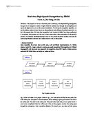
Figure 5.3
Figure 5.3 is basically a block diagram of system as how it will perform encryption and decryption.
A same table will exist at decrypter end and that will also compare it and then play the corresponding 8 bit value.
Now again comes in the issue of latency of RAM, normally it takes 17 clock cycles in comparing and transmitting one value which is pretty much acceptable.
- Implementation Design and Constraints
Different approaches were used to implement the design. Every Implementation scheme had its own advantages and disadvantages which led us to use other platforms.
-
MATLAB Implementation
MATLAB was our first preference as an implementation platform. MATLAB provided us with the first working prototype of the system design. After the first prototype we were confronted with the limits problem. MATLAB was unable to support keys above 16 bits. Moreover time taken for each calculation was of significant concern.
- C Implementation
In order to resolve the problems presented by MATLAB, The algorithm was implemented on C, where as MATLAB served as an interface. Now the sound was recorded and saved in a text file by MATLAB, C read the specified file and saved the encrypted values in a separate file. This file is then read by decrypting side and is decrypted. The final values are now again saved in a file and this file is read and played by MATLAB again.
But still key length was an issue as C only provided us with a key length of 32 bits. Moreover this technique was not very suitable for Real Time conversations.
Figure-5.4
Now the computation time was reduced to 0.023 seconds per sample and 8000 samples could be calculated in 68.31 seconds.
- Maple Kernel
MATLAB provides us the services to access and use Maple Kernel. Maple is general purpose software which can be used to perform complex mathematical calculations. Maple provided us with a technique to break up keys and values in structures this enabled us to use any key length and observe the behaviors.
Figure-5.5
The provided line graph provides us with the calculation timings using Maple Kernel. Now the time taken per sample was 0.031 seconds and 8000 samples will take 70.83 seconds.
Apparently, MAPLE seems to be less efficient, as compared to the C implementation. Yet it may be worth noting that these computational times are for (256, 32) bit keys.
- Comparative Analysis
Provided below is comparative analysis of different techniques and their impact on decrypted signal. All the times recorded below have been measured on a 1.8 Mhz Pentium Class Processor and all results have been averaged over 10 samples.
Figure-5.6
Figure-5.6 shows the original sound signal provided to Encrypter side. This signal has been sampled over 11025 samples per seconds.
Figure-5.7
The figure-5.7 is the encrypted signal. This is intermediate result. It is output of encrypter and serves as input for decrypting side.
Figure-5.8
Figure-5.8 is basically is latency free diagram of output but it is the scenario where Real time Constraints are not considered.
Figure-5.9
Figure-5.9 above shows the impact of latency on the received signal. As we can see though the signal is almost distorted yet still we can extract exact information to some extent.
Figure-5.10
Figure-5.10 illustrates the output signal if we pre calculate the values. Here we can get a delayed version of the sound signal, but once signal has started there is no intermediate latency.
- Experimental Observations
Now, following is the comparative analysis for the time required for the processes like Public Key Generation, Evaluation of d and for Decryption.
5.6.1 Public Key Generation
Figure-5.11
Figure-5.11 provides us the calculation of time required to generate public key N and signature e in seconds
5.6.2 Calculation of “d”
Figure-5.12
Figure-5.12 depicts the calculation timings of “d” in various cases and key lengths.
- Encryption Timings
Figure-5.13
Figure-5.13 shows the time taken by system in encrypting one sample with a specific key length.
Bibliography
[1] The Data Encryption Standard (DES) and its Strength against Attacks by D.Coppersmith.
[2] Advanced Encryption Standard by Adam Berent.
[3] Announcing the AES by Federal Information Processing Standards Publication.
[4]
[5] RSA Encryption by Tom Davis
[6] A Method for Obtaining Digital Signatures and Public Key Cryptosystems
by R.L Rivest, A. Shamir, and L. Alderman.
[7]
[8] A Handbook of Cryptography by A. Menezes, P. Van Oorschot and S.
Vanstone, CRC press 1996.
[9]