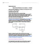
For current to flow, and the circuit to be complete, components must be joined by a conductor such as wires or tracks.
- To measure the amount of current through a component, we use an ammeter.
- To measure the p.d. across a component, we use a voltmeter.
The Resistor
Resistors can be used to reduce the current in a circuit. The higher the resistance of the resistor, the lower the current that it allows to flow. As a result, they are often used to protect other components in a circuit. Resistance is measured in ohms.
To measure resistance colour banding is used:
Resistor values are identified by four bands of colour. Resistance is measured in ohms (). The first ring gives the 1st number of the resistance; the second ring gives the second number of the resistance. The third ring tells you what to multiply this number by and the fourth gives its tolerance (accuracy).
First ring: yellow = 4
Second ring: purple = 7
Third ring: red = x 100
Forth ring: gold = 5% tolerance
So the resistor = 4700 or 4.7 k
The Diode
Diodes are processors which allow current to flow in one direction only. This is because they have a low resistance if connected the correct way around, and a very high resistance if connected the wrong way around. As a result, they are very useful to protect components which would easily be damaged if a power supply was connected the wrong way around. Diodes could be used to test if a battery is connected the correct way around.
Logic Gates
Logic gates are processors which make simple decisions based on inputs. There are three main types of logic gates - AND, OR and NOT.
In a logic gate, a logic 1 means the current is above a certain value. A current less than this value is at a logic 0.
AND gates – give an output at logic 1 if both inputs are at logic 1.
OR gates – give an output at logic 1 if either inputs are at logic 1.
NOT gates – give an output at logic 1 if the input is at logic 0.
Truth tables
Truth tables are used to show us the possible combinations of inputs and outputs for a logic gate.