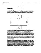
In conducting this experiment there was very little to be taken into account in terms of safety. The current and voltage we were using were very small and so had no dangerous implications.
RESULTS AND OBSERVATIONS:
Below is the table of our results. We took 3 readings and took an average to try and achieve a greater deal of accuracy. The measurements we took were to 1 decimal place as this was the greatest deal of accuracy we could be sure of with the equipment we were using. Our figures for the average and the resistance were taken to 3 decimal places, as we could be surer of the accuracy of these results. One thing that I noted during the testing was that despite using a 6volt battery the voltage was actually only 5.7 volts. This can be put down to the fact that the batteries might have already been used and already lost some power. Another observation I made was that between 0 – 40 degrees the voltage read 0. This could be because when the slider was in this position it was somehow touching the other terminal causing the current to bypass the potentiometer (taking the route of least resistance). Because the voltmeter was connected in parallel to the potentiometer and the potentiometer was being missed out of the circuit, it read 0. This short circuit also caused a surge in current which meant that the current was off the scale.
We started measuring at 40 degrees as this was the point at which the current had dropped to a readable level and the voltage had returned to its normal level. We finished testing at 290 because this was the maximum distance that the potentiometer could turn.
In order to make these results easier to interpret I plotted them on a line graph of resistance against movement. This allowed me to see any relationships between the two far more easily.
ANALYSIS:
The first thing we checked for was systematic errors. We could find no zero error as the instrument was pretty accurate. Also we could detect no random fluctuations in the equipment.
From the graph we can see that there is a relationship between the amount of movement and the resistance. As the amount of degrees moved increased the resistance increased. The increase in resistance was caused by the fact that as the contact was moved more of the coils were exposed and there were more of them for the current to travel through. In a series circuit such as the one we used resistance increases as the length of a resistor increases (in this case the coils). So for example if the length of the resistor is doubled then the resistance is doubled. This happened to a degree in our experiment.
To find the sensitivity of the potentiometer I used the gradient of the graph to find the ratio. This is just the change in resistance over the change in degrees. However the gradient of the line varied slightly. This meant it was possible to draw 2 different gradients on the graph. This showed that the potentiometer was more sensitive in some areas than it was in others. For example between 40 and 200 degrees it had an average gradient of 0.2 ohms increase for every 10 degrees movement (or 0.02 ohms for every degree.) Whilst between 200 and 290 it had an average gradient of 0.2 ohms per 7.5 degrees (or 0.026 ohms per degree). I would say that this shows that the potentiometer isn’t actually that sensitive because only a small change in resistance is produced by quite a large movement (as a fraction of the total movement possible). The varying sensitivity could be caused by…
When looking at resolution, the resolution of the sensor depends on the scale of the measuring devices. For example the smallest unit on the scale of our instrument was 0.1 mA. This means that the potentiometer might be able to detect very small movements but they wouldn’t be big enough to produce a movement of 0.1mA and so we wouldn’t know that it could resolve movements of that size. When testing for the resolution we once again found that the resolution was better in some areas than in others. I found the average resolution in 4 different areas: Between 40 -70 degrees, 70 – 130 degrees, 130 – 230 degrees and 230 – 290 degrees.
I calculated the resolution by finding the total movement in degrees in a region. I then found the difference in the average current for the two interval boundaries of the region. I then divided the total movement by the difference in current. This gave me the amount of degrees moved to produce a change of 0.1mA (the smallest change in current that my ammeter could detect.) Below are the calculations for the resolution of the potentiometer.
40 degrees to 70 degrees movement.
40 – 70 = 30
95.6 – 47.6 = 48
30 / 48 = 0.625
A movement of 0.625 degrees produced a change in current of 0.1ma
So 0.625 degrees is the smallest movement that can be resolved in this region.
70 degrees to 130 degrees movement.
130 – 70 = 60
47.6 – 22 = 25.6
60 / 25.6 = 2.344
A movement of 2.344 degrees produces a change in current of 0.1mA
So in this region 2.344 degrees is the smallest movement that can be resolved.
130 degrees to 230 degrees movement.
230 – 130 = 100
22 – 11.3 = 10.7
100 / 10.7 = 9.346
A movement of 9.346 degrees produced a change in current of 0.1mA
So in this region 9.346 degrees is the smallest movement that can be resolved.
230 degrees to290 degrees movement.
290 – 230 = 60
11.3 – 8.3 = 3
60 / 3 = 20
A movement of 20 degrees produced a change in current of 0.1mA
So the smallest movement that can be resolved in this region is 20 degrees.
This shows us that the potentiometer goes from being extremely sensitive and being able to detect movements off less than a degree to being very irresponsive and only being able to detect movements of 20 degrees. This could be down to the fact that…..
I found that the response time for the potentiometer was extremely quick because as soon as there was a movement of the arm there was a change on the reading of the ammeter and there was no fluctuation in the display after that. Although it was impossible to accurately measure the response time of the sensor I can use background knowledge to estimate its response time as about 1 /10th of a second
CONCLUSION:
From the analysis of the results we can see that the properties of the potentiometer are: a good sensitivity in some areas and a bad sensitivity in others; a large variation in resolution throughout its range of movement; short response time.
This information makes it quite difficult to suit the potentiometer to a particular purpose. For example if it was to be used as something such as a fuel gauge it wouldn’t be able to give reliable readings because it has such a short response time that every time the petrol in the tank moved it would give a false reading. Also the fact that it has a differing resolution could be useful or a problem. For example where it has a very high resolution it would give a very accurate reflection of the fuel level whereas when the resolution is low it would eliminate the fluctuations caused by the petrol moving around in its tank.
One use which this potentiometer would be suited to is something such as the mechanism which is used to change how well toast is cooked. It would be good for this purpose as the quick response time doesn’t matter. It doesn’t have to be that sensitive or the resolution doesn’t have to be that good
Overall I was quite pleased with the accuracy of our experiment. There were a few slightly anomalous results which can be seen on the graph as the bumps or dips in the line. They were almost certainly down to human error in either, the moving of the arm on the potentiometer or reading the figures from the ammeter. Also these anomalous results seem to appear in groups, which is probably due to the fact that when one false reading was made this caused a few other readings to be slightly out.
If I were to conduct this experiment again there would be quite a lot I would change. Firstly I would have to find a better way of measuring the angle that the contact had been moved. I felt that the method we used was adequate but it was quite inaccurate because there were a number of stages where human error could play a part. Firstly when marking the degrees on the card it would have been quite easy to put the mark in slightly the wrong place. Also it would be quite easy to move the arm to far or not far enough which would cause misleading results. Another problem area was the method we used to secure the potentiometer. We clamped it to the table so that it didn’t move whilst the slider was being moved, however it was easily possible that it could have slipped causing a deceptive set of results. One way to eliminate these errors as much as possible would have been to take more sets of results before taking an average.
This investigation could be extended to look at linear potentiometers and potentiometers of different power ratings to see how the properties of different types of potentiometer would compare to one another.