Formula:
I=V/R
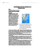
IF we look at this picture above we can see that there is an attraction between positive and negatively charged bodies. The potential that these charges have for doing work if they come together is called voltage (V).
()
Temperature
We know that as temperature increases the resistance increase as well this is because when we increase temperature we are giving more kinetic energy to the ions and they vibrate around which causes some problem to the electrons; as they are obstructed by the vibrating ions. When that power level is sufficient to raise the temperature to above 1000 degrees Kelvin, visible light is produced. As the power dissipated is increased, the amount of light increases and the peak wavelength of the light shift to the blue (colour of the filament changes from red to bright white). Typical filament lamps have temperatures ranging from 1800 to 2700 degrees Kelvin. The light from the low temperature lamps appears reddish yellow while the high temperature lamps have a `whiter' appearance.
The tungsten filament evaporates more rapidly as the temperature of the filament goes up. The evaporated tungsten particles tend to deposit on the glass envelope, causing over time, an increase in light absorption. Depending on the application, the light output obstruction could be high enough to end the useful life of the lamp. Eventually, the filament material will evaporate enough to cause the filament to break, completely ending the life of the lamp. Both of these effects are strongly dependent on the temperature of the filament, which is why long life filament lamps tend to be operated at the low end of the temperature range and the light has a yellowish appearance.
(Gilway.com)
The electrical resistance of the tungsten filament at room temperature is initially quite low. When electrical power is first applied to the lamp, a large in-rush current causes rapid heating of the filament. The resistance of the filament rises to a value five to ten times the cold resistance, which causes the amount of current drawn by the lamp to stabilise and the lamp to emit a stable light output. Depending on the size of the filament, the in-rush period can be from tens of milliseconds to hundreds of milliseconds. This in-rush current requirement should be taken into account in the selection of the power source for a specific lamp application.
(Gilway.com)
Converting between Celsius and Kelvin:
You can convert between Celsius and Kelvin like this:
Kelvin = Celsius + 273.15
Scientists use the Kelvin scale, which is based on the Celsius scale, but has no negative numbers. Zero on the Kelvin scale is considered the be absolute zero; that is, the point at which all molecular motion stops. (http://www.usatoday.com/weather/wtempcf.htm)
Few ways to measure the temperature of filament lamp
- You could measure the wavelength of the light emitted from the filament lamp
- You could use the equation
- You could use the graph
1.1-The Nature of Radiation (measuring the wavelength)
All objects above the of to their surrounding environment. This energy, or radiation, is emitted as that travel at the . Many different types of radiation have been identified. Each of these types is defined by its . The wavelength of electromagnetic radiation can vary from being infinitely short to infinitely long
It’s pretty hard to accurately measure the wavelength of light. The problem is that the wavelengths are very small. The wavelength of visible light is about 1 millionth of a meter. In order to accurately measure the wavelength of visible light you need a sensitive tool called a spectrometer.
With the help of a prism, you could roughly measure the wavelength of light being filtered out by the coloured wrap. To do this, you'll first need to measure the spectrum of the original light source. Start by passing the light through a small vertical slit. You can make this out of cardboard by cutting a slit, say, 10 cm tall and 1/2 cm wide. Then pass the light from this slit through a prism. Shine the resulting 'rainbow' on a white piece of paper and carefully note the colours that are present (it would be helpful to do this in a very dark room). Then, do the same experiment, but place the filter between the light and the slit. Carefully note the colour(s) that are missing. You can then use these rough numbers to determine the wavelengths that have been filtered out:
Violet: 400 nm (1 nm = 1 nanometer = 1 meter/1,000,000,000)
Blue: 500 nm
Green: 550 nm
Yellow: 600 nm
Red: 650 nm
The of maximum emission of any body is inversely proportional to its absolute temperature. Thus, the higher the temperature, the shorter the wavelength of maximum emission.
When we got a rough estimate of the wavelength at various points, we can use Wien's law to find the temperature. Wien's law suggests that as the temperature of a body increases, the wavelength of maximum emission becomes smaller
The formula for Wien’s law is:
1.2-To use the equation to find the temperature
There are various temperature formulas that we can use to find the temperature, I will show you two different equations to find the temperature. Firstly I will show you the temperature coefficient formula and then I will show you the Stephan-Boltzmann formula. The temperature coefficient of resistance is simple a measure of how the resistance of a piece of material changes with temperature. For metals, as the temperature increases, the resistance increases, due to the increased movement of the atoms in the metal.
Resistance of a conductor is directly proportional to temperature. This is because with the increase in temperature, vibration motion of the atoms of conductor increases. Due to increase in vibration, probability of collision between atoms and electrons increases. As a result, resistance of conductor increases.
So therefore:
(1) Increase in resistance of a conductor is directly proportional to original resistance.
ΔR ∝ R1..............(a)
(2) Change in resistance is directly proportional to change in temperature.
ΔR ∝ΔT…(b)
combining (a) and (b) we get:
ΔR ∝R1. ΔT
ΔR = (constant) R1ΔT
Here constant = a
ΔR = a R1ΔT
Where a = temperature coefficient
As ΔR = R2 - R1
and
ΔT = T2 -T1
We get
R2 – R1 = αR1 (T2 – T1)
R2 = R1 + αR1 (T2 – T1)
R2 = R1 {1 + αT2 – T1)}
When T1 = 0 and T2 = t
Rt = R0 [1 + α((t – 0)]
Rt = R0 {1 + αt}
TEMPERATURE COEFFICIENT Fractional change in resistance per unit original resistance per degree change of temperature is called temperature coefficient
ΔR = aR1ΔT
α = ΔR / R1 ΔT UNIT 1/ K OR 1/ 0C
Stephan-Boltzmann Law states that the amount of given off by a body is proportional to the 4th power of its temperature as measured in Kelvin units. This law can be expressed by the following simple equation:
P = eσAT4 Watts
e is the emissivity of the surface (a number between 0 and 1, being 1 for a perfect black body),
σ is the Stefan-Boltzmann constant, the accepted value for which is 5.672 x 10⁻⁸ W/m2.T4
A is the surface area of the body in m2, and
T is the absolute temperature of the body in K.
1.3-Useing the graph to find the temperature
Firstly we need to find the potential difference and current of the filament lamp at various points, from our result we got to draw a I/V characteristic graph for a filament lamp.
Problem identified:
I have decided to investigate into the resistance of a filament lamp. I will measure the current and potential difference of the filament lamp at various points, after measuring current and potential difference I will draw a graph to show the relationship between current and potential difference. By finding 1 over gradient of the I/V characteristic graph we can work out the resistance of the filament lamp. When we found the resistance of the filament lamp we can compare resistance of the filament and the power supplied to it with the potential difference. From that we can get an estimate of the temperature for different potential difference.
Prediction:
I predict that by increasing the resistance we will also increase the temperature of the filament lamp. Also the filament is not an ohmic conductor.
This is because we know that at high temperature the ions have more kinetic energy then they would have if the temperature was low, so therefore the ions vibrate and obstruct the electrons, that increase the resistance.
Key variables:
Dependent:
I will be estimating the temperature of the filament lamp for different potential difference. The units for temperature will be Kelvins, for voltage it would be Voltage.
Independent:
- Voltage
- Current of the filament
- Temperature
- Resistance
- Power
Control Variables:
- Length of the filament
- Material type of the filament
- Cross-section area of the filament
- Current of the power supply
Safety precaution:
- Electricity is dangerous so therefore be careful while connecting the circuit by having the power supply turned off at start.
- Make sure that the current is not too high, which will cause the filament bulb to blow up and that is not safe working.
All typical safety rules for lab work should be followed. These include no running whilst experiments are in progress, hair tied back, jewellery tucked away and carrying out all experiments on benches clear of school books and standing up with stools tucked under benches. Also, as the potential difference is increased the more the current flows through the circuit. As this happens, it is extremely likely that the apparatus shall become hot, so particular care should be taken whilst handling it.
Fair test:
In order to make the results as accurate as possible, each reading should be repeated at least three times, and the mean of these three should be taken as the final reading. This would increase accuracy, by repeating the experiment we will remove any anomalous result.
The same pieces of apparatus should be used for each repeat, as even a slight variation in a piece of the apparatus. To make this experiment fair, we need to control the control variables.
Circuit diagram:
Apparatus:
- Ammeter
- Voltmeter
- Variable Resistor
- Filament lamp( 12V)
- Connecting Wires
- Crocodile clips( 2- to 3 to connect the
- Thermometer
- Power supply (D.C supply 12V)
Preliminary Measurements:
To get an idea of what range of measurements would get the best results, I done a preliminary experiment where a circuit was set up using all of the apparatus which would be included in the final experiment.
We know that the filament lamp is 12V, the maximum potential difference of the bulb would be around 12V also the maximum temperature of the bulb would be around 12 Volts so therefore I decided to set the power supply to 12V.
After choosing the DC voltage power supply, I had to choose different ranges of voltage each time, I concluded that it would be best to start from 0.5 volts and to finish at 12 volts, increasing in steps of 0.5 volts each time. This would give me quite an extensive range of numerical results. This range had been repeated two more times, I could work out the mean current, voltage and from the mean of voltage and current I could work out the average resistance. Once I had discovered the average resistance, I could plot this value on the graph. When all the values had been plotted on the graph, a line of best fit could be drawn.
Experimental Errors:
We know that no experiment gives the right answer, but scientist aim to get near and near to the right answer. So therefore my experiment will have some errors which we have to battle against.
I will measure the current to 2 significant figure this is because in my preliminary experiment I found out that the ammeter was fluctuating, so therefore I decided that it would be best to measure current to 2 significant figure. I will measure the voltage to 3 significant figure, this is because if the voltage of the filament lamp was 12.04 volts then if we were measuring to 2 significant figure then the value would be 12 volts which is not very accurate so therefore it would be precise and accurate to measure the voltage to 3 significant figure. I will find the percentage error of my result to show how accurate my results are.
Method:
- Get the apparatus that are listed above
- Connect the connecting wires to the DC power supply
- Set the power supply to 12V
- Make sure the power supply is off
- Now connect ammeter to the power supply by the connecting wires
- Connect the ammeter to the filament bulb by the use of connecting wires
- Now connect the filament lamp to the variable resistor
- Connect the variable resistor to the power supply by the mean of the connect wires
- Connect the voltmeter to the filament lamp
- Make sure the voltmeter is connected parallel to the filament bulb
- Also make sure that ammeter and variable resistor is connected serially in the circuit.
- Make sure that the voltmeter and the ammeter are connected into the circuit correctly.
- Once your circuit has been checked switch on the power supply.
- Check if the circuit works, and the ammeter and voltmeter is giving you write values. If the values are negative then you have connected ammeter and voltmeter wrong way.
- You can change the value of the voltage across the lamp by changing the resistance of the variable resistor; this will also change the value of the current.
- Start with a low value for the voltage (0.5volts) and measure the corresponding value of the current.
- Read the values for current and voltage and record them on a table
- Repeat steps 1 to 17 two more times.
- Once all the required values had been gained, the three separate results for each voltage were added together and divided by three, in order to find the average current
-
These values were then plotted into a I/V characteristic graph
Results:
Analysis of Results:
The graph is showing the relationship between the average voltage and the current in a filament lamp produces a curve. The curve begins very slightly at first and then gradually becomes steeper. It shows that as the voltage was increased, the current that was flowing through the wire also increased. There were some anomalous results, the reason for these result could be random errors where mine reading and recording of the results were wrong.
Conclusion:
If you look at the colour of the filament at various points you should notice that the colour changes from red to shinny white. This indicates that the temperature of the filament lamp is increasing at every point. From my re-search we know that the mamimum temperature of the filament lamp is around 3,000 Kelvin, and at this temperature the colour of the filament lamp is shinny white. At 12V the colour of the filament lamp was shinny white which tell me that the maximum voltage of the filament lamp is around 12V. The room temperature was 23 Celsius, to convert this into Kelvin we add 273 to it. So the room temperature in Kelvin was 296; this was also the temperature of the filament lamp at 0volts.
Remember this is an estimate not an accurate answer, if you use the graph we could find the temperature at various points. For example if the want to know the temperature of the filament lamp at 6.50Volts, to do this you have to use the I/V characteristic graph where you read 6.5 volts horizontally and go up. Where 6.5 volts touch curve you read of the temperature value from there. So the temperature at 6.5 Volts would be 1500 Kelvin.
If the Voltage of the filament lamp was
In my re-search I showed 3 different way to measure the temperature I will use Stephan-Boltzmann formula to
As I said in my perdition that as the temperature of the filament increase so will the resistance increase?