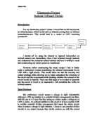
I intend to have my whole circuit operating off a power supply of 5 volts. The chip I used is 7474 which incorporates two D type flip-flops. I used this chip because I will be using it in the circuit as a latch so that when it receives a clock pulse it will let a high voltage through . To set the chip, pin 4 has to detect a change of low to high voltage (0.8v-2v). To reset the chip, pin 1 has to detect a change of high to low voltage (2v-0.8v). The infrared sensors I used for my circuit gave out a high voltage of about 4V when sensing infrared and a low voltage of about 0.2mV when in the dark.
For my preliminary circuit the LDR I used for the setting of the circuit had a resistance of 960Ω when in light and a resistance of 5.2KΩ when in darkness. I used a resistor of 4.7KΩ with it in the potential divider. I calculated what value the resistor would be by using the formula: V=I*R.
Resistor value:
In light: 23000+4700=27700Ω
5/27700=1.8e-4I
1.8e-4*4700=0.85V
In dark: 5200+4700=9900Ω
5/9900=5.1e-4I
5.1e-4*4700=2.37V
This potential divider has a voltage output of 0.85V in the light and 2.37V in the dark.
The LDR I used for the resetting of the circuit had a resistance of 270Ω in the light and a resistance of 1.4KΩ in the dark. I used a resistor of 270Ω with it in the potential divider. The calculations for the resistor are:
In light: 350+270=620Ω
5/620=8.1e-3I
8.1e-3I*270=2.21V
In dark:1400+270=1670Ω
5/1670=2.9e-3I
2.9e-3*270=0.81V
This potential divider has a voltage output of 2.21V in the light and 0.81V in the dark.
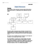
For my final circuit the infrared sensor I used for the setting of my circuit had to be placed into a transistor switch arrangement because of the behaviour of the infrared sensors. I put a resistor in a potential divider arrangement with the IR sensor with a value of 100KΩ and another resistor at the output of the transistor with a value of 2.2KΩ. However due to the time constraints I was unable to construct another transistor switch with an IR sensor as the resetting mechanism of the circuit. I used the transistor because including an IR sensor in a potential divider will not present me with the required outputs, as a result I used the transistor to deal with the unusual behaviour of the IR sensor.
Finally I decided that I would use an LED as an indication of the state that the circuit is in. I wired the LED to a 100Ω resistor in series so that the voltage across the LED would be 1.7V and not 5V which would be too high for the LED. The transistor I used was a Bc 109 and had the pin setting of 1=emitter, 2=base and 3=collector.
The circuit
Test Results
I firstly began testing by checking whether my D type flip-flop worked or not. I did this by wiring up the chip to a power supply of 5V. then wired up the set(pin 2) on the chip to a 5V and I connected the output of the chip(pin 5) to the external voltmeter on the bench. I then wired the clock input of the chip(pin 3) to 5v. When this was done the output of the chip changed from 0V to 5V indicating that the setting of the chip worked correctly. I then earthed the reset (pin 1) of the chip while disconnecting pin 2. this led to the output reverting back to zero. This meant that the resetting of the chip worked correctly as well.
I also tested whether the potential divider portions of the circuit worked correctly. I connected the setting potential divider up to 5V and the output to the voltmeter on the bench. When the LDR was uncovered the voltage output was 0.85V, while when it was covered the output was 2.37V. This meant that the setting potential divider would correctly set the chip. I then tested the resetting potential divider with the same method and found that when the LDR was uncovered the output was 2.21V while when it was covered the output was 0.81V. This part of the circuit was also compatible with the chip and would successfully reset the circuit.
I then tested the infrared sensors. I did this by wiring them up to 5V and the voltmeter on the bench. When there was no infrared source the output of the sensors was 4.8V while the output when using an infrared source was practically 0V. This meant the sensors were working to their specifications. I also tested the transistor by placing it upon the testing socket on the multimeter and setting it to hfe. The reading given out was 500 which was within the range of 200-800 which I was expecting meaning the transistor worked.
The final tests I did involved having the whole circuits wired up to 5V. with the preliminary circuit when the reset LDR was covered and the setting LDR was uncovered the LED would light up meaning the setting of the circuit worked( 5V was coming from the output of the chip when measured). I then covered the set LDR and uncovered the reset LDR. This time the LED went out meaning the resetting of my circuit worked. This meant the whole circuit worked and I could move onto the intended circuit with infrared sensors.
I then replaced the setting potential divider with the infrared/transistor switch. When the reset LDR was covered and the IR sensor received infrared the LED came on. This meant the switch and IR sensor were working to set the circuit. I then removed the IR source and uncovered the reset LDR the whole circuit reset. Due to the time limit I couldn’t replace the resetting potential divider portion of the circuit.
Assessment of performance
In the end both my preliminary and final circuits worked. With the circuit containing the LDRs the circuit worked exactly to my specifications and worked 100% of the time. The setting and resetting of the circuit worked during every test of the circuit while each component passed their individual tests.
The second circuit didn’t fully reach my specifications. This was due to the fact that I didn’t install an IR sensor with transistor switch for the resetting role of the circuit. Therefore the LDR from the previous circuit remained. The setting portion of the circuit did fulfil my specifications and passed tests 100% of the time as well. While the infrared sensor and transistor worked fully to their potential.
Overall the circuits were 100% reliable and fulfilled their specifications I was disappointed that I couldn’t replace the reset LDR on the second circuit with a IR sensor.
Acknowledgements
During the construction of my circuits I received help from my subject teachers who are Mr.Laird and Mr.Payne.
Mr.Payne helped me with the initial concept of my circuit while also suggesting making the preliminary circuit and helping with the construction of the circuit.
Mr.Laird helped me with the IR sensors and suggested the idea of using the transistor switch while helping me with the construction of the final circuit.
I also used the internet to research about IR sensors and transmitters. One website which was www.winniepegrobotics.com had detailed information about how infrared worked and the various uses of infrared.