SHEEP
COUNTER
by
Ian Kemp
August
2000
Sheep Counter.
Aim
This project is designed to meet the need of a busy sheep farmer. Counting sheep can be a time consuming and awkward task and so a solution to this problem would be to make an electronic counter so that every time a sheep passes through a gate the counter would add one. However, it must only count up one when the sheep has actually passed through the gate, e.g. if the sheep pauses in the middle of the gate the counter should not go up one.
Research
The gate needs to be wide enough for the sheep to be able to easily pass through and yet not so wide that more than one sheep at a time can get through. To find out some details of the physical size of sheep I e-mailed a sheep farmer that I know, Mr Shepherd.
A screen shot of my e-mail is shown below.
In the reply that I received from Mr Shepherd, he advised me that for the width of the sheep in the flock, most are about 40 cm wide, with some of the larger ones being as much as 50 cm. He also said that, the light beam needs to be about 45 cm above the ground so that it will be able to detect both the larger, mature animals and also the smaller lambs.
I therefore intend designing my system for a gate that is 60 cm wide as it will ensure that it works properly for 50cm.
Specification
My system must be able to reliably detect sheep passing through the 60cm wide gate and not be affected by any ambient conditions.
My system must be able to count up to at least 999 and be capable of being reset to zero.
My system must operate from 12 volts, since this is readily available from the farm vehicles.
It must also consume little power since it must not provide a drain on the farm vehicles batteries. I therefore want my complete system to have an average current consumption of less than 100mA.
Generation of possible solutions
There are several ways in which this could be achieved.
(a) A small device to emit a radio signal could be attached to each sheep so that as it goes through the gate, a radio receiver detects the transmission and increments a counter. The problem with this is that it would be expensive to put a radio transmitter on every sheep and the batteries would have to be regularly changed in each of the sheep transmitters.
(b) A tuned circuit could be attached to each sheep so that as it passes through the gate an oscillator attached to the gate post and at the same frequency as the tuned circuit, would loose energy. Such a loss could be detected and then used to increment the counter. This is the principle used by many shops to deter and catch shop lifters and is again expensive to fit each sheep with the required tuned circuit.
(c) A light beam could be set up across the gate way so that as the sheep breaks the beam, the counter is incremented. This method requires nothing to be attached to each sheep and so is the cheapest and easiest system to implement. It is this system that I will investigate and use for my system.
I can use either a Light Dependent Resistor (LDR) or a photodiode for my light beam sensor, and either Light Emitting Diodes (LEDs) or a filament lamp for my light beam producer. Filament lamps are not very efficient and consume too much power. Since this equipment must be battery operated it is essential that it should be as low a power as possible. I am going to therefore use LEDs. Looking through the Rapid Electronics catalogue, there is an 8mm diameter red LED with a rated output of 4.5 candela, which is the brightest one that I have been able to find.
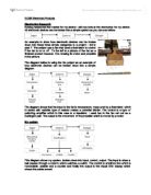
For a light sensor I am going to use a LDR, since I have used them before in my class work and know how to use them in circuits. To find details of the characteristic curve of the LDR I consulted the RS Components catalogue CD ROM and found a data sheet for the LDR, type NOPRP12. (Data sheet file number 232_3816.pdf). A table of the electrical characteristics and a graph of resistance against illumination are shown below, as extracted from the data sheet.
To test the range of the LDR and LED I set up the following circuits.
The resistor R1 was calculated as:
The maximum current through the LED is 30mA. The forward voltage drop is 1.85V.
Therefore the voltage across R1 is 12 - 1.85 = 10.15V
So R1 = 10.15/0.03 = 338.
The nearest preferred value available was a 390 resistor which I used.
The power dissipated by the resistor will be approximately given by
But with the LED only on for half of the time, the mean power is half of this value, so a 0.25W resistor will be suitable.
I measured the light level in the lab where I was working and also outside, and found that the illumination inside was 650 lux and outside 5,000 lux. This corresponded to resistances of 1000 and 200. Using a value of R2 of 1k and the LED, I found that I could achieve
a voltage change of 1V when the LED was 30cm from the LDR. When I repeated the test outside I found that I could only achieve a change of 1V at a distance of 10cm, due to the additional ambient brightness. Changing R2 to 220 had little effect to the overall range of working. I therefore concluded that this was not going to work.
When I discussed the problem with my supervisor he advised that I should look at the section B question in the summer 2000 examination for the old AS electronics syllabus. The system diagram ...
This is a preview of the whole essay
a voltage change of 1V when the LED was 30cm from the LDR. When I repeated the test outside I found that I could only achieve a change of 1V at a distance of 10cm, due to the additional ambient brightness. Changing R2 to 220 had little effect to the overall range of working. I therefore concluded that this was not going to work.
When I discussed the problem with my supervisor he advised that I should look at the section B question in the summer 2000 examination for the old AS electronics syllabus. The system diagram from the question is shown below and represented a method of making remote measurements of temperature.
This gave me the idea of pulsing the LED at a frequency of approximately 1kHz, and then amplifying just the alternating component of the voltage across the LDR. Unfortunately when I looked again at electrical parameters of the LDR I realised that it has a very slow rise and fall time, amounting to almost 100ms. This would give a maximum useable frequency of 10Hz.
Sub-system development and system details
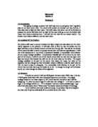
My complete sheep counting system will therefore consist of the following sub-systems shown in the diagram below.
I envisage that the system will work in the following way. The astable will make the LED flash at a rate of about 10Hz. This flashing light will pass across the gap in the gate and modulate the light intensity arriving at the LDR. The small varying voltage produced by the change in resistance of the LDR will then be amplified to produce a 10Hz pulses. These will be sent to a missing pulse detector The pulse detector circuit will produce a logic 1 output when the 10Hz pulses are no longer present. The output from the pulse producer will then increment the counter every time it goes to an output of logic 1.
The astable sub-system
The easiest way to make a LED flash at 10Hz is to use a 555 IC arranged as an astable. The circuit diagram is shown below which I obtained from the Foundation Electronics support booklet.
I want to make the LED flash with an On/Off ratio as near to 1:1 as possible as it will make the pulse detector easier to design. It is not possible to achieve a perfect 1:1 ratio with a 555 but a good approximation can be achieved by making R1 = 1k and R2 = 1M.
The frequency of the astable circuit is given by
The nearest standard value to this is 100nF, which will give a frequency which is lower than 10Hz.
I have already calculated a suitable value for R3 on page 4 and will use a 390 resistor.
I assembled the components onto a prototype board. A labelled photograph of the protoboard showing the layout is shown on page 7.
When connected to a 12V supply the astable worked first time and the LED began to flash. The pulse rate was measured using an oscilloscope and the period of the flashing was 112ms. This is a frequency of 8.9Hz. Changing the supply voltage to 10V resulted in no measurable change to the frequency of flashing.
At 12V the current consumption was 6mA when the LED was off and 32mA when the LED was on.
As far as could be measured using the oscilloscope, the mark to space ratio was 1:1.
This sub-system therefore seemed to work satisfactorily and the next stage is to work on the LDR circuit.
I constructed the circuit shown opposite and measured the voltage changes across the resistor, R2, with the oscilloscope set to ac input. This enabled the sensitivity of the oscilloscope to be increased without any problems from the larger direct voltages across the resistor. I also experimented with different values of R2 and found that in bright light, a 470? resistor gave the largest alternating voltage output.
With the astable circuit and the LDR circuit operating from the same power supply, I found that there was a signal visible on the oscilloscope even when the light from the LED was completely blocked from the LDR. When I discussed this with my supervisor he suggested that the variation in current from the power supply caused by the LED switching on and off was causing a small change in voltage which I was observing in the oscilloscope. I tried connecting a 100?F capacitor across the power supply, but it had little effect. I therefore decided to use a separate power supply for the transmitter and receiver. I also had problems when the fluorescent lights were switched on in the lab, as the LDR picked up the fluorescent lamps switching on and off at 100Hz with the alternating current. Because the rest of the class did not like working in the lab without the lights on, I tried to reduce the signal produced by the fluorescent lamps by
first connecting a 1?F capacitor across the resistor and secondly by putting a tube around the LDR to shield it from the lamps.
At a distance of 60cm between the LED and LDR, I could detect a signal of approximately 200mV. A photograph of the trace is shown below.
Because the waveform is so slow it was difficult to actually take the photograph while the trace was on the screen. The y-sensitivity was set to 50mV per division and the time base was set to 20ms per division.
The next sub-system to consider is an amplifier to increase the signal from the LDR. Looking again at the examination question I found the circuit for a possible amplifier which I have printed below.
This is an inverting amplifier with a voltage gain of -100. Because I am using very low frequencies and do not want to use a large value coupling capacitor to the LDR I will modify this circuit to be non-inverting since it will have a very large input resistance. Again
because I am using low frequencies I can allow the amplifier to have a very high gain so that it will saturate on pulses received from the flashing LED. I will therefore aim for a voltage gain of 1000.
My circuit diagram for the amplifier and LDR is shown below.
When the circuit was first tested it was found to have a noticeable output in the absence of any signal from the LDR at 50Hz. This I suspected was a result of the high voltage gain and lack of shielding enabling the amplifier to pick up 'mains hum'. I tried various capacitors across the 1M? feedback resistor of the op-amp to reduce this and found that a 10nF capacitor worked well enough to reduce the mains hum signal in the absence of a light signal without reducing the size of the pulses when the light signal is present.
At a distance of 60cm between the LDR and LED, the output signal was a series of pulses from 1.5V to 10.5V. A photograph of the oscilloscope trace is shown below.
In this photograph the y-sensitivity was set to 5V per division.
With this sub-system working successfully I now need to design a circuit to act as a pulse detector. As part of the course I had already
constructed a simple timer using an op-amp as a comparator and a capacitor and resistor that discharged. The circuit diagram for the timer is shown below.
I can modify the circuit so that the pulses from the amplifier keep the capacitor charged so that it is always above half of the supply voltage. When the pulses are stopped, by the light beam being broken, the voltage across the capacitor will decrease to below half of the supply voltage and the output of the op-amp will go low. In fact I need it to go the other way round so that when the pulses disappear the output must go high. I can easily achieve this by reversing the input connections to the op-amp.
I decided to replace the switch with a diode from the output of the amplifier so that when the output of the amplifier was saturated positively, the capacitor would charge quickly, but would effectively disconnect the capacitor from the amplifier when the output went low. The capacitor would then discharge through the 1M? resistor. It needed to discharge to 6V in approximately 0.05s, which will take approximately 0.7RC.
The nearest preferred value to this is 100nF.
The complete circuit so far is now shown below.
When the pulse detector was connected to the circuit it worked as expected so that when the light beam was broken the output of the op-amp went high.
The next stage is to add the counting system. Originally I had intended to build a counter and use seven segment displays to indicate the number of sheep that had passed through the gate, but I found that it was difficult to see the display when in bright light, and with 30mA per segment, each display could need up to 210mA. With three displays, a significant current is required from the battery. I discussed this problem with my supervisor who reminded me that mechanical counters are available, which not only are easily visible in bright light but also retain the count when the power is removed. This seemed to be a good idea. I therefore had a look on the RS Components web site, rswww.com, to see what was available. The screen shot below shows the page with the counter.
Though expensive, the cost is not that much more than it would be using large, bright seven segment displays, and electromagnetic counters do have the advantage that the count will not disappear as soon as the power is removed.
However, if I am going to use one of these counters I will need to produce a driver circuit to interface the op-amp to the counter since it requires approximately 100mA to activate it. I decided to use a transistor as a switch and since the counter is an electromechanical device, the transistor will need protecting using a diode. I remembered from my earlier measurements of the output voltage of the TL071 op-amps, that when the output voltage is low, it is still at 1.5V, which is more than sufficient to keep a transistor permanently switched on. I looked in the support booklet to see if there was any
mention of how to overcome the problem, and found solutions on pages 45 and 46. I decided to use a potential divider to reduce the voltage appearing at the base of the transistor when the output of the op-amp is low. The complete circuit diagram is now shown below.
When I asked my supervisor to order one of the electromechanical counters he said that he already had an ex-equipment counter that should satisfy my needs. I tested it in a 12V supply and it counted reliably. I measured the current passing through it when power was connected and found that it was 120mA, which made it safe to connect to my system.
Testing the system
To test the complete system I set the system up in the lab with the transmitter placed on one table and the receiver placed on another table so that there was 60cm between the LED and the open end of the tube housing the LDR. Power was applied to both the transmitter and receiver. The transmitter was clearly working because the flashing LED was clearly visible but it took some time to align the receiver to the transmitter. Eventually they were both aligned and the counter stopped 'chattering', as it had done while the system was being adjusted. Each time an object was passed through the beam the counter increment by one, which showed that the system worked.
I then decided to test it outside in daylight. It was an overcast morning and the system performed much as in the lab, except that it was even more difficult to align the transmitter and receiver. By the afternoon, the weather was much better and so long as the system was not operating with the LDR in direct sunlight, it continued to work. If the LDR was in direct sunlight then the system failed to work. Taking the system back into the lab, the following measurements were made on the complete system.
Measurements
Transmitter.
Supply Voltage (V)
Current (mA)
Flash rate (Hz)
3.8
6.5/35
8.9
2.0
6/32
8.9
0.0
5/30
8.9
Receiver.
Supply Voltage (V)
Current (mA)
Flash rate (Hz)
3.8
28/152
8.9
2.0
25/146
8.9
0.0
22/135
8.9
The range that the system operated over depended to some extent on the ambient lighting levels, but apart from when the LDR was in bright sunlight, the system was able to reliably detect objects passing through the beam over a gap of at least 60cm.
Speed of operation is not an issue since it takes at least 2 seconds for a sheep to pass through the beam completely, and the system easily responds in that time.
Assessment
Overall I am pleased with the performance of my system. It fulfils the criteria that I initially required except for when the LDR is in bright sunlight. It is able to detect objects passing through the 60cm gap and the complete system is able to operate from 12V sources, though the transmitter and receiver power source must be separate to avoid interference passing along the power supply lines. The power requirements are modest, 35mA, peak, for the transmitter and 152mA peak for the receiver. The total peak power consumed by the complete system, assuming a fully charged car battery would be calculated using
The mean power would be considerably less than this value. The average 60Ah battery would be able to keep the system operating for several days. The mechanical counter also has the advantage that it retains the count after the power has been disconnected.
While designing and constructing the system I used a 12V regulated power supply with a current limit of 500mA. As a result I did not feel that I needed to take any special precautions to ensure the safety of my equipment, my self or my class friends. However a lead acid battery is a completely different matter, since they do not have any current limit facility, the short circuit current being of the order of 1000A. It is clear that extra precautions will be necessary to ensure that the system and operators are safe. Before connecting the system to a tractor battery a 1A fuse MUST be incorporated into the circuit so that in the event of a fault, the fuse will fail so protecting the system, the battery and the operator.
Limitations and Modifications
There are three limitations of the current system,
(a) the system is difficult to align
(b) the system needs two batteries to operate
(c) the system does not work when the LDR is in bright sunlight
(a) To overcome the first difficulty I will build a transistor switch, connected to the output of the first op-amp, which will operate an LED. This will mean that when the transmitter and receiver are aligned, this LED will flash in sympathy with the transmitter LED.
(b) To overcome the second difficulty I will experiment with putting a small resistor and a large decoupling capacitor on the receiver power supply, so that any low frequency ripple from the transmitter's flashing LED is removed.
(c) To overcome the third difficulty I will put the LDR in a longer and more opaque tube with a lens, to focus the light from the transmitter LED.
Modifications
(a) To connect an LED to the output of the amplifier, I used a similar circuit to the one I used for driving the electromechanical counter, except that it was not required to switch a large current or need to be protected against any induced voltage.
(b) To remove low frequency noise from the power supply I connected a 10? resistor in series with the positive power lead and a 1000?F capacitor from the positive to 0V lead.
The complete modified circuit diagram is shown below.
(c) To over come the problem with direct sunlight, I experimented with using a longer and more opaque tube over the LDR with some success, although when the sun was low in the sky and shining into the tube, the counter failed to function. Adding a lens gave little improvement over a longer tube. The only real solution is to ensure that the gate to which the sheep counter is attached is so aligned that direct sunlight onto the LDR is not possible.
The pictures below are of the completed receiver with just a short tube on the LDR.
Evaluation of the final system
With the proviso that the system is only ever used in conditions where direct sunlight cannot reach the LDR, the system meets the original specification.
It allows a beam of light to pass across a distance of 60cm;
It increments a counter every time the beam is broken;
It is operated from a 12V car/tractor battery;
It will count up to more than 999;
The average current consumption is less than 100mA.
Acknowledgement
I am grateful for the assistance of Mr Shepherd, who helped and provided advice on the sizes of sheep, Mr Lamb, the lab technician who obtained the parts and components for the project and to my supervisor, Mr Eweing, for the advice he offered during the course of this work.
I also made use of the following publications and electronic resources,
The RS Components web site and CD catalogue,
The Rapid Electronics catalogue,
The support booklet for the Foundation Electronics Module,
Past examination papers from NEAB, AS Electronics
Based on a project by Gemma Gittins, Llanfyllin High school.
Candidate's record of the supervision of coursework.
NAME:-........Ian Kemp........................................................................................
REFERENCE NUMBER:-.......123450996789..................................................
On each occasion when you and your supervisor discuss your coursework, details of the consultation should be recorded. The record should begin as soon as you start on the coursework, i.e. when the form of the experimental project is being chosen and should be completed when the written report is submitted to your supervisor for assessment.
Date when discussion took place
Content of discussions; advice, guidance and help given by the supervising teacher.
270700
Initial discussion with Mr Eweing on various projects.
Decided to investigate building a sheep counter.
020800
Project aim agreed with supervisor.
040800
Discussed range problems with Mr Eweing. He suggested looking at the summer 2000 NEAB EL01 examination paper.
060800
Discussed phantom signals from the LDR even when flashing LED was obscured. He suggested it may be noise on the power supply from the transmitter and to use separate power supplies.
080800
Discussed counter/display with Mr Eweing. He suggested that I should investigate electromagnetic counters.
00800
Project demonstrated to supervisor.
20800
Demonstrated modifications to Mr Eweing.
60800
Final project report submitted to supervisor.
I certify that the above is a record of the candidate's work.
Supervisor's signature:..........R. Eweing...................Date:...240800....
7