Generation of possible solutions:
I could use 2 light dependant resistors to detect the difference in light reflected from the line. It would react quite slowly
I could use two phototransistors which emit infrared beams onto the line. When less light is detected on the phototransistors there is less resistance thus allowing the motors to move.
Sub-system development:
My circuit had two designs combined. First is the line follower, which detects light and moves according to the line, and the other part is a bump sensor which when it stumbles across an obstacle it reverses, this is because the switch had been pushed when it hits an obstacle.
I have decided to place two LEDs where the motors are, this is so that the LEDs will indicate which direction it is turning towards.
The input is the phototransistors, they detect the light and depending on how much light/resistance there is, activates the motors to move which is the output.
Component Layout:
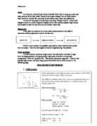
Having the schematic completed I realized that my robot should be able to travel in a straight line and turn around corners, including sharp corners and reverse when it bumps into an obstacle. It will use an audio amplifier (LM386), a resistor of 1KΩ to 47KΩ, a capacitor with values from 10μF to 100 μF. I will use a PNP transistor (2N3906 or PN2907), a DPDT relay and two motors. The LM386 is a power amplifier that is used on low voltage applications. The gain is internally set to keep external part count low, but the addition on an external resistor and capacitor between pins 1 and 8 will increase the gain of any value up to 200.
In order for the robot to work I will need to use two phototransistors. These will be placed on either side of the line. The phototransistors depend on light. When more light is reflected on the LED there is less resistance, the circuit will have more current flowing through it. This makes the motors turn and so the robot advances forward. This also means that if less light is on the LEDs, or no light, there is high resistance, little current passes through the circuit. The motors do not move resulting in the robot being stationary.
So in my circuit the phototransistors are constantly shining down. So when the infrared is being emitted on the white background it reflects the light so the LEDs sense light reflected on them. This makes the motors free to move and so the robot follows the line. When the robot reaches a corner in the line, it will turn towards the line. This is because when it reaches a turning point, one of the phototransistors is reflecting on the white background while the other on the black background. The colour black absorbs light; the infrared beam is being emitted on the black line is not being reflected back. The motor connected to the LED on the black line will slowdown and eventually stop. The LED on the white background however is getting light reflected on it because the colour white has the ability to reflect all light. The motor connected to the LED on the white background is running. So we have one motor moving and one motor not moving. These results in the robot changing direction and turning towards the Led on the black line, therefore the robot will have turned to follow the black line. This is how the robot will maneuver around corners and follow the line.
Two IR emitters (phototransistors) are put in a comparator circuit of which there is an audio amplifier which for this circuit is being used as a motor driver.
The phototransistors sense differences in light reflected on them. One of the phototransistors is connected to the inverting output and the other to the non inverting output. If both are equal the output should be 4.5. But if the phototransistor on the non inverting input receives more light the output will be more than 4.5. If the phototransistor on the inverting input receives more light the output will be less than that of 4.5.
The phototransistors work when there is a difference in light regardless of how much light there is on it.
The other section is a bump sensor. If the line follower robot hits an obstacle it will know and will back up and reverse. So it the robot goes of course, it will reverse back and carry on following the line. This works because the switch activates a transistor which in turn activates a DPDT relay sending the motor in reverse. Whilst this is happening the capacitor is being charged. So when the switch reverts to being in its normally open condition (when it has backed away from the obstacle) it will continue to do this until the capacitor is fully discharged.
Construction: When constructing the circuit I had to understand the schematic drawing. As I didn’t have a breadboard layout I had to figure out myself where to place each component. I had to take into consideration where to place each pins of the transistor. I also had to be careful when using the soldering iron to solder on the wires to the relay. I had to carry out all safety procedures to ensure that there was no risk of any damage. When testing my components I made sure that I used a resistor as well, this was so that there was not too much voltage passing through which could have blown up the component. There are two parts so the circuit. One is the line follower which is connected to the two motors. The other part is the bump sensor which reverses the motors when it hits an obstacle. Both parts are connected to the two motors; one side makes it move forward while the other reverses it.
Testing: I tested the line follower robot by using light and covering the phototransistors. I noticed that when one phototransistor received more light, the motor connected to the other phototransistor (the one will less light) slowed down. When I covered both phototransistors the motors slowed don and stopped. This showed that the robot works as it followed the light. I also used an ammeter to check the current passing through the circuit. This confirmed that my circuit was working correctly. When I covered the phototransistors the there was around 0.4 A passing through. However, when I applied light onto the phototransistors (using an ordinary LED) I noticed that the reading on the ammeter was 8.6 A. this proves my theory that covering the phototransistors, it increases the resistance.
Evaluation: My circuit works well and follows my specification. The motors move forward when light is placed and it and slow down when no light is present on the phototransistors.
- Robot has the ability to move in s straight line, around curves and turn corners.
- With the photo transistors it can follow a black line against a white background.
- It works using a 9V battery
- It has a relay which reverses the direction of the motors turning so it can move away from obstacles
- It doesn’t require anyone to move it or guide it using a remote control.
- It is light and easy to move so when it goes of course I am able to put it back on the line
- Has two LEDs which indicate what direction it is turning