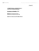
Fig. 1: Exterior
Composition of Space
Villa Muller is a house designed by Adolf Loos in
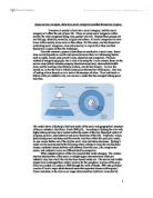
1930. Its interior is extremely complex, composed of discrete spatial episodes. Villa Muller cannot be explained merely with plans alone or sections alone. There is a complete overlap of plans and
Fig. 2: Section
sections in Villa Muller, as spaces are boxes which are displaced asymmetrically in the villa. Adolf Loos said, “Every room needs a specific height -- the dining room a different one from the pantry, therefore the floors are on varying levels.” In Villa Muller, different rooms of different functions have different height and are located at different levels. The living room, “Marble Hall”, is two times the height of the anteroom of the villa. The dining hall is 7 steps above the datum of the Marble Hall, which the kitchen and pantry are also on this same level. Such composition, more interestingly, creates four to five levels within Villa Muller, which is actually a two storey high building. Such composition is created by varying heights of rooms according to their functions, and positioning them according to a methodology: The plan of the villa is divided into 3 equal rectangular parts. The first part is at the lowest part of the site, which contains the garage, storage rooms and the servants’ rooms. The next part rises a level up, which
consist of laundry facilities and boiler room. The last part rises another level up, which is the entry point of the villa. Together, these three parts of different levels constitute one complete rotation. The rotation continues upward with three levels, each rising a consistent height from the previous level: the marble hall, then to the dining room and kitchen, and finally the boudoir and library. This completes the second rotation. The spiral stops at the flat plane of the bedroom level. Such methodology is used to define basically and position spaces within a house, not just creating
space without order and reasoning.
Definition of Space
Fig. 3: Marble Hall
There are many features created by Loos within each room of the villa to define the room distinctively. Different features are placed in the room to create a sense of closure for each space in the villa, notably distinct cladding materials, stabilizing room-specific symmetries, thresholds marking the points of entry and etc. For example, in the Marble Hall, the room is outlined by beams and is symmetrically composed, with marble slabs marking the longitudinal center of the room. The center in transverse direction is marked by a single door which leads to the terrace. There is also a distinct material palette in the hall. Cipolin were cut into panels and used on finished structural columns, pilasters, sides of windows and the stepped wall to the dining room. Such elements mark strongly a sense of a distinctive space. The dining room, next to and on a different level than that of the Marble Hall, is another discrete space, which has features which differs from the Marble Hall to define itself as a different space. There is also a mark between the two spaces, which a solitary riser divorced from the run of the main stair becomes a threshold of the space and serves momentarily to delay entry into the room. Also notable is that certain rooms do not require walls to distinct and separate between each other due to the distinct markings in each space.
The experience through the villa is led by the stairs. Upon entering the villa, a narrow corridor leads towards a generous anteroom. Path winds up a staircase and around two corners to the level of the Marble Hall. The staircase then divides into two branches: with one branch leading along the edge of the marble hall up to the dining room. The kitchen and pantry are also on this same level. The stairs are positioned in a central shaft, skylit from the roof terrace,
Fig. 4: Staircase
continues up half a level to the boudoir. In the end, the stairs reaches flat plane of the bedroom level, which the level consists of the master bedroom and tightly-configured quarters for the live-in servant.
The rooms of the villa are connected with connecting spaces. The connecting spaces goes through the edges of each room. The rooms intervene these connecting spaces as their materials extends out towards these connecting spaces. For example, the ceramic tile floor in the entry lobby sweeps beyond the doors to claim the adjacent anteroom. The marble cladding of the Marble Hall extends into the neighboring territory, sheathing the pedestal and stretching in opposite directions into the slotted recesses of the stairs. This marks the influence of the rooms towards the connecting spaces. The connecting spaces also imply a displaced meaning. Lines of movements in these connecting spaces are never the same with the axes of symmetries of the rooms. Using an example to illustrate the effect of this, the Marble Hall can be entered through a framed entrance by paired columns and pilasters and a vista through a distant window, but after a few steps into the hall, the axis of motion by the frame is displaced by the axis of the room due to the implications of axial center by the marble slabs mentioned previously.
Conclusion
Adolf Loos said, “This is the great revolution in architecture: the solution of the plan in space, just as mankind will eventually succeed in playing chess in the cube, so too other architects will, in the future, solve the plan in space.” Adolf Loos’ Villa Muller is a great execution of his idea of “Raumplan”, the planning of space in a more free way without the constraints of the idea of storey. Moreover, the articulations and markings of space through datum shifts, material pattern cladding and distinct demarcations of axis of individual rooms have been successfully carried out, defining individual spaces distinctly from other spaces. Villa Muller is a great example of space planning and defining, exhibiting the prominent effect of organizing and demarcation of space.
Reference
1, 2. Leslie Van Duzer & Kent Kleinman, Villa Muller: a work of Adolf Loos, (New York: Princeton University
Press, 1994)
Fig. 1.
Fig. 2.
Fig. 3.
Fig. 4.