- Readings are recorded in another table. When the variable resistor has reached the end or there are sufficient results, the current can be directed backwards again for negative readings.
The results should then be presented graphically, as the outcome of the line will show the relationship between the current and voltage. A straight line will show the
component does obey ohms law as the current is constant and proportional to the p.d. A gradient can be calculated to determine the resistance.
A curved graph will show the alternative, that it is not an ohmic conductor. The p.d and current are not proportional.
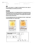
Ohms law can be presented mathematically by the equation V = IR which can be compared to the equation of a straight-line graph to calculate the gradient and find the resistance.
V = R I
↓ ↓ ↓
Y =m x + c
The graphs will be set out as follows, showing the negative axis along with positive.
Results:
Filament Lamp
Positive Negative
Resistor
Positive Negative
Analysis of results:
The graph for the filament lamp produced a curved line showing no proportionality and that the lamp is not an ohmic conductor. A resistance cannot be calculated because it is not constant.
The graph for the fixed resistor produced a straight line. Which means the current – voltage relationship is proportional and it is an ohmic conductor. A resistance can be calculated because it is constant.
Gradient = ΔΥ = 3.5 = 15.2Ω
ΔΧ 0.23
Conclusion:
Ohms law is only applicable when the temperature is kept constant. The graph for the filament lamp had a curved line. The filament got hotter as the current increased and therefore the resistance increased. Because the temperature and current were not constant, the filament lamp is not an ohmic conductor. The gradient of the curve is very small at the beginning showing that there is little resistance. However as the current increases, the gradient of the curve increases too. The resistance is changing due to this change in current and temperature.
Overall it is possible to determine two main things. Firstly, the filament lamp is not an ohmic conductor, and secondly, the resistance becomes more constant as the current increases.
The fixed resistor produced a straight-line graph. Instantly from looking at the graph it is clear to see that the current – voltage relationship is constant. The resistor is an ohmic conductor. Because of this it was possible to determine a value for the resistance from the gradient. The value was said to be about 15Ω and I obtained 15.2Ω, which is a fair value.
This also shows that the experiments were carried out accurately. Sufficient results were obtained to produce graphs and determine if each component were an ohmic conductor. Some of the results in the tables may have been slightly anomalous but overall appeared correct. Any errors that may have occurred in the experiment were probably due to human error rather than systematic error. These could include errors when recording readings off the ammeter or voltmeter or when rounding off numbers, which would give minimal error. There was not much that could go wrong in the experiment once it was set up accurately and everything was checked to be in working order.
The experiment could have been repeated and an average set of results could be made to plot graphs, but I don’t think it is necessary and may have just wasted time.
Task 2
An atom has three parts - neutrons, protons and electrons, set out as below
Electrons revolve around the protons and neutrons continuously. When an electron ahs enough energy(this could be from the voltage), it can break free from the outer orbit to become a free electron. When an electron leaves an atom the atom is then more positively charged and is unbalanced. Thus it will always want to get an electron back to the valence orbit to become balanced. As electrons are negative they will always be attracted to a positive atom. This continous movement of electrons, as atoms gain and lose one, is the current.
What happened with the filament lamp is that as the p.d was increased, the filament got hot due to the increase in current. As the current increased the chance of free electrons bumping into atoms was increased and they did, causing vibrations. As the atoms vibrate more they relaese their potential energy in the form of kinetic energy, and they then take in the heat as energy and vibrate even more causing more heat to be produced. The vibration of the atoms impedes the flow of electrons, therefore changing the resistance, which increases. Because of the changes in temperature and resistance the filament is non – ohmic.
The fixed resistor didn’t get as hot as the filament lamp when the current was increased. The fixed resistor may be made out of a material with a higher melting point so the atoms are more stable as well. As the atoms are not vibrating as much, the flow of free electrons is not impeded and resisitance stays constant. Hence it is an ohmic conductor.
Task 3
The potential divider is used to supply a variable p.d. Therefore a desired level can be obtained. The potential divider can allow the voltage across a component to be varied continuously between 0v and the battery voltage by use of a sliding contact. Whereas a rheostat varies the resistance, it is designed to resist current flow. Because it has a maximum resistance it does not allow the voltage across a component, or the current through it, to be reduced to zero. A rheostat is also quite bulky and dissipates the surplus energy in the form of heat so it can get very hot.
Task 4
1a) V =IR
I = V/R
I = 8/4
I = 2a
b) Current is constant, therefore I = 2a
- V = IR
V = 2 x 3
V = 6V
- V = IR
R(total) = 3 + 4
R(total) = 7Ω
V = 2 x 7
V = 14V
2a) R(total) = 2 + 3 = 5Ω
- I = V/R
I = 10/5
I = 2a
- V = IR
V =2 x 2
V = 4V
- V = IR
V = 2 x 3
V = 6V
- Terminal pd. = E – IR
E = terminal pd. + IR
E = 10 + 2 x 1
E = 12V
4a) 1/R(total) = 1/R(1) + 1/R(2)
1/R(total) = 1/3 + 1/6
1/R(total) = 3/6
R(total) = 6/3 = 2Ω
- V = IR
V = 6 x 2
V = 12V
- 12V
- I = V/R
I = 12/3
I = 4a
- I = V/R
I = 12/3
I = 4a
- Current across parallel resistors = 0.9a
V(across 5Ω resistor) = IR
Current is constant in series circuit = 0.9a
V = IR
V = 0.9 x 5
V = 4.5V
V(across parallel resistors) = 12 – 4.5
V = 7.5V
I = V/R
I1 = 7.5/30
I1 = 0.25a
Need to find the total resistance of the parallel resistors
V = IR
R = V/I
R = 7.5/0.9
R = 8.3Ω
Equation for 2 parallel resistors must be rearranged to find r.
1/R(total) = 1/r + 1/r
1/R = 1/30 + 1/r
1/r = 1/R – 1/30
1/r = 8 1/3 – 1/30
1/r = 3/25 – 1/30
1/r = 13/150
r = 11.54Ω