Rachael Barlow Physics Coursework
Finding the Spring Constant of a Copper Spring Using a Potential Divider
1.0 Aim
To undertake an experiment to assess the behaviour of a potential divider as a sensor.
2.0 Objectives
- Build and test a sensor.
- Explore the characteristics of the sensor.
- Calibrate the sensor.
3.0 Introduction
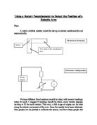
The system, which I am using to find the constant of a spring, could be used for quality control in industries where springs are made. Potential dividers are used in strain gauges in buildings to calibrate subsides. The potential divider in the circuit is going to be used as a position sensor. A potential divider is simply two resistors, across which a voltage is applied, with the output being taken from the junction of the resistors. If a single variable resistor is used for R1 and R2, then the output voltage can be varied, and this is the basis of the volume control.
4.0 Method
A potential divider will be placed in the middle of a 25cm long ruler at 12.5cm. A hole needs to be drilled through the centre on the ruler at 12.5cm to attach and hold the potential divider. To the left-hand side of the ruler a small hole will be used to thread some wire through to produce a pivot. At the opposite end of the ruler two holes will be drilled. The hole at the top right will be drilled to hook the spring onto, then at the bottom right to attach the weights to. Two clamp stands will hold the ruler at a height where the weights will not touch the surface when 10N are applied.